skoda Workshop Repair Guides

Skoda Workshop Service and Repair Manuals

Replacing and adjusting the vacuum setting element for exhaust gas turbocharger on engines with identification characters BJB (O > < Checking the charge-air system for leaktightness (Superb II, Octavia II, Fabia II, Roomster)
Replacing and adjusting the vacuum setting element for exhaust gas turbocharger on engines with identification characters BLS (Superb II, Octavia II)
Special tools and workshop equipment required
t  10 mm wrench socket -T10422-
t  Ring spanner 10 x 12 -T10423-
t  Adapted fixed spanner 14 mm → Fig.
t  Hand vacuum pump, e.g. -VAS 6213-
t  Turbocharger tester -V.A.G1397 A-
t  Pressure control valve -VAS 6342-
t  Feeler gauge 0.05 mm → Electronic Catalogue of Original Parts
   
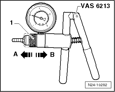
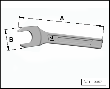
Adapt fixed spanner 14 mm
t  A = 110 mm
t  B = 25 mm
–  Adapt the dimensions of the fixed spanner 14 mm as shown in the illustration.
  Caution
The special tools listed, in particular the socket wrench -T10422-, must be used exclusively as described below and must not be used for any other screwed connections. Risk of deformations, opening and slipping of the wrench at higher tightening torques.
  Note
In order to replace the vacuum setting element, the spare part set is used → Electronic Catalogue of Original Parts.
Removing
–  Remove cover and bulkhead plenum chamber → Body Work; Rep. Gr.66.
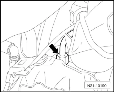
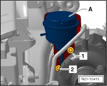
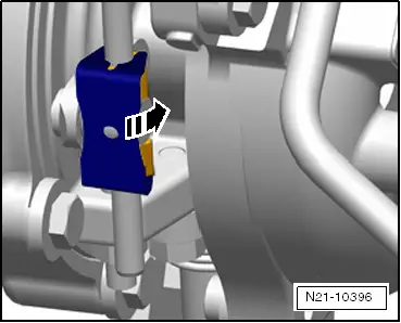
–  Remove the connecting pipe for the crankcase ventilation from the cylinder head cover, to do so press together the release buttons.
–  Remove intake hose to exhaust turbocharger:
t  Vehicles Superb II and Octavia II → Chapter.
t  Vehicles Fabia II and Roomster → Chapter.
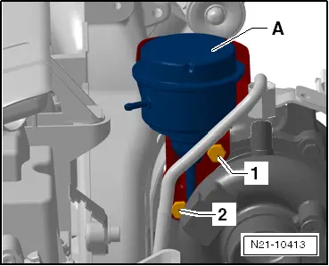
–  Close the inlet opening of the exhaust gas turbocharger with a screw cap from the spare part set.
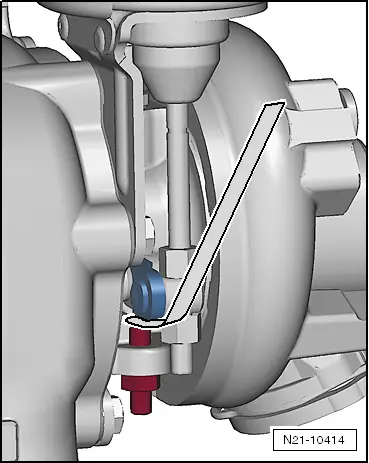
–  Detach vacuum line from vacuum setting element for exhaust gas turbocharger.
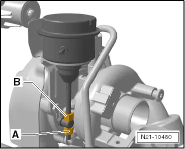
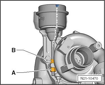
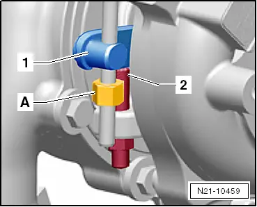
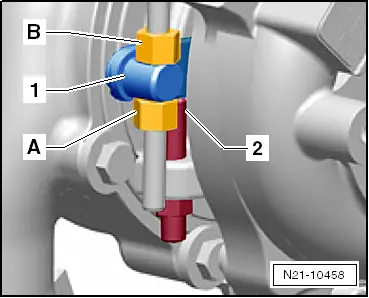
  Caution
When slackening the union nut of the oil feed line, it is absolutely essential to counterhold the connection fitting on the exhaust gas turbocharger with the adapted fixed spanner 14 mm.
  N21-10357
–  Unscrew the union nut of the oil feed line -arrow-, to do so counterhold the connection fitting on the exhaust gas turbocharger with the adapted fixed spanner 14 mm.
–  Close the opening of the connection fitting on the exhaust gas turbocharger with a plug from the spare part set.
  N21-10190
–  Counterhold the counternut -B- with ring spanner -T10423- and unscrew the fixing nut -A- from the control rod with socket wrench -T10422-.
  N21-10460
–  Unscrew screw -1-, then screw -2- and remove vacuum setting element -A-.
Install
  N21-10413
–  Mark the opposite position of the pressure box of the vacuum setting element and the control rod in the released position, as shown, in different colours.
  Note
The colour marking makes it possible to check the opposite position of the pressure box of the vacuum setting element and the control rod once more after tightening both nuts on the control rod and, if necessary, to correct any twisting.
  Caution
Only use new screws and nuts from the spare part set.
–  If necessary, remove the fixing nut from the control rod of the new vacuum setting element.
–  Screw the counternut onto the control rod of the new vacuum setting element by hand up to the thread end and pull the control rod through the opening of the adjusting lever on the exhaust gas turbocharger.
  N21-10470
–  Move the vacuum setting element -A- in its installed position and screw in screws -1- and -2-. Tightening torque 8 Nm.
Setting
–  Switch on the turbocharger tester -V.A.G1397 A- and position the sliding switch to position “I”, and read the measured value of the atmospheric pressure in mbar.
–  Deduct 600 mbar from the indicated atmospheric pressure and note as “value 1”.
–  Deduct 650 mbar from the indicated atmospheric pressure and note as “value 2”.
  N21-10415
–  Fit together the hand vacuum pump -VAS 6213- with the pressure control valve -VAS 6342- as shown in the figure and connect at the connection “I” of the turbocharger tester -V.A.G1397 A- as well as at the vacuum setting element.
–  Connect the lever -1- at the pressure control valve -VAS 6342-.
  A21-10668
–  Position the sliding ring -1- of the hand vacuum pump -VAS 6213- to position -A- for vacuum.
  Caution
Risk of damage to the pressure box from excessive vacuum. The pressure of the read off atmospheric pressure must not be less than 800 mbar.
  Note
t  An accuracy of ± 20 mbar is sufficient when setting the “value 2”.
t  Ensure that the adjusting lever of the exhaust gas turbocharger moves smoothly on the control rod.
–  Operate the hand vacuum pump -VAS 6213- repeatedly until the noted “value 2” is shown on the turbocharger tester -V.A.G1397 A-.
  N24-10282
–  Set the noted “value 1” accurately by opening the lever -1- of the pressure control valve -VAS 6342-.
–  Screw the fixing nut -A- a couple of thread turns onto the control rod.
  Note
t  When starting the following work step, ensure that the adjusting lever of the exhaust gas turbocharger -1- will rest on the adjusting screw -2- and does no longer lie on the fixing nut -A-.
t  If this is the case, turn back the fixing nut -A-.
  A21-10668
–  Hold the adjusting lever -1- fully on the adjusting screw -2- by hand.
  N21-10459
–  Slowly unscrew the counternut -B- of the control rod by hand until it makes contact with the adjusting lever, do not turn further.
–  Turn the fixing nut -A- on the control rod against the adjusting lever of the exhaust gas turbocharger -1-.
  Note
When tightening the fixing nut -A-, ensure that the control rod does not twist.
–  Counterhold the counternut -B- with the ring spanner -T10423- and tighten the fixing nut -A- with a 10 mm socket wrench -T10422-.
  N21-10458
–  Check the colour markings applied on the vacuum unit as well as on the control rod:
l  The markings must be flush.
  N21-10470
–  Release the vacuum, to do so slide the sliding ring -1- of the hand vacuum pump -VAS 6213- into position -B- for pressure and then once more into position -A- for vacuum.
  N24-10282
–  Position the feeler gauge of 0.05 mm, as shown in the figure, between the adjusting lever and the adjusting screw.
–  Now operate the hand vacuum pump -VAS 6213- until the feeler gauge of 0.05 mm is jammed between the adjusting lever and the adjusting screw.
–  While doing so, read the pressure on the turbocharger tester -V.A.G1397 A-.
Specified value: The noted “value 1” ± 20 mbar.
The value is o.k.
–  Use seal paint from the spare part set to seal the connection of the control rod/fixing nut.
  N21-10414
–  Press the lock washer on the control rod by hand and turn it 90° in -direction of arrow-.
The value is not o.k.
–  Repeat the adjustment procedure → Anchor.
Complete installation
Further installation occurs in reverse order for removal, while paying attention to the following:
–  Remove the plug from the connection fitting on the exhaust gas turbocharger, install the oil feed line and tighten the union nut to 22 Nm.
–  Remove the screw cap from the inlet opening of the exhaust gas turbocharger.
–  Start engine and erase fault memory → Vehicle diagnosis, testing and information system VAS 5051.
  N21-10396

Replacing and adjusting the vacuum setting element for exhaust gas turbocharger on engines with identification characters BJB (O > < Checking the charge-air system for leaktightness (Superb II, Octavia II, Fabia II, Roomster)