skoda Workshop Repair Guides

Skoda Workshop Service and Repair Manuals

Fuel preparation system Diesel injection > < Replacing and adjusting the vacuum setting element for exhaust gas turbocharger on engines with identification characters BLS (S
Replacing and adjusting the vacuum setting element for exhaust gas turbocharger on engines with identification characters BJB (Octavia II)
Special tools and workshop equipment required
t  Pliers for spring strap clamps
t  10 mm wrench socket -T10422-
t  Ring spanner 10 x 12 -T10423-
t  Hand vacuum pump, e.g. -VAS 6213-
t  Turbocharger tester -V.A.G1397 A-
t  Pressure control valve -VAS 6342-
t  Feeler gauge 0.05 mm → Electronic Catalogue of Original Parts
  Caution
The special tools listed, in particular the socket wrench -T10422-, must be used exclusively as described below and must not be used for any other screwed connections. Risk of deformations, opening and slipping of the wrench at higher tightening torques.
  Note
In order to replace the vacuum setting element, the spare part set is used → Electronic Catalogue of Original Parts.
Removing
   
–  Lift the engine cover at the sides -arrows 1- and pull out towards the front -arrow 2-.
  S10-0209
–  Disconnect vacuum hose -3- from mechanical exhaust gas recirculation valve and hose to vacuum setting element of intake manifold flap. Expose vacuum hoses -arrow-.
–  Disconnect pipe to crankcase ventilation -4- at air guide pipe.
–  Release spring strap clips -1- at exhaust turbocharger.
–  Release screws -2- and -5- and remove air guide pipe.
–  Remove connection pipe of exhaust gas recirculation → Chapter.
–  Detach the connecting hose and remove the inlet connection → Chapter.
–  Remove the sound dampening system → Body Work; Rep. Gr.50.
–  Detach vacuum line from vacuum setting element for exhaust gas turbocharger.
  S10-0303
–  Counterhold the counternut -B- with ring spanner -T10423- and unscrew the fixing nut -A- from the control rod with socket wrench -T10422-.
  S21-0176
–  Unscrew screw -1-, then screw -2- and remove vacuum setting element -A-.
Install
  S21-0177
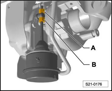
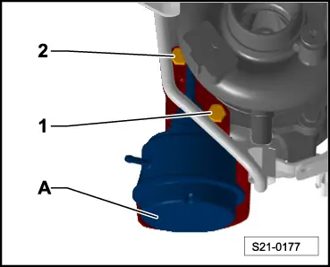
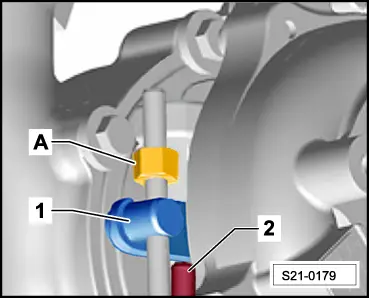
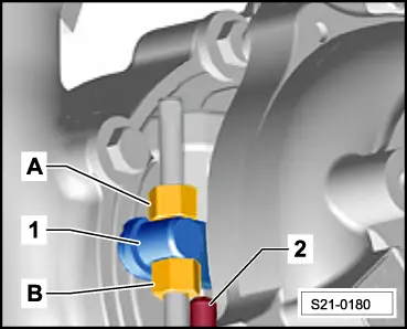
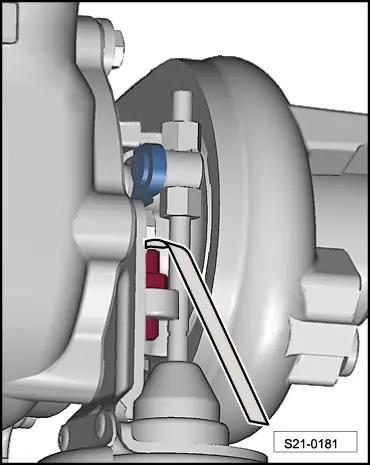
–  Mark the opposite position of the pressure box of the vacuum setting element and the control rod in the released position, as shown, in different colours.
  Note
The colour marking makes it possible to check the opposite position of the pressure box of the vacuum setting element and the control rod once more after tightening both nuts on the control rod and, if necessary, to correct any twisting.
  Caution
Only use new screws and nuts from the spare part set.
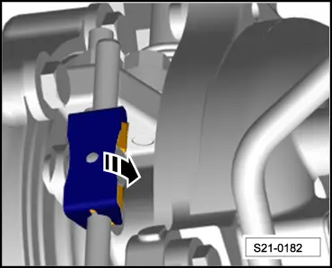
–  If necessary, remove the fixing nut from the control rod of the new vacuum setting element.
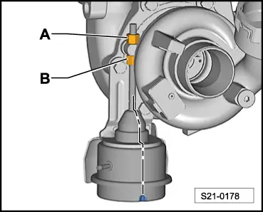
–  Screw the counternut onto the control rod of the new vacuum setting element by hand up to the thread end and pull the control rod through the opening of the adjusting lever on the exhaust gas turbocharger.
  S21-0178
–  Move the vacuum setting element -A- in its installed position and screw in screws -1- and -2-. Tightening torque 8 Nm.
Setting
–  Switch on the turbocharger tester -V.A.G1397 A- and position the sliding switch to position “I”, and read the measured value of the atmospheric pressure in mbar.
–  Deduct 600 mbar from the indicated atmospheric pressure and note as “value 1”.
–  Deduct 650 mbar from the indicated atmospheric pressure and note as “value 2”.
  S21-0177
–  Fit together the hand vacuum pump -VAS 6213- with the pressure control valve -VAS 6342- as shown in the figure and connect at the connection “I” of the turbocharger tester -V.A.G1397 A- as well as at the vacuum setting element.
–  Connect the lever -1- at the pressure control valve -VAS 6342-.
  A21-10668
–  Position the sliding ring -1- of the hand vacuum pump -VAS 6213- to position -A- for vacuum.
  Caution
Risk of damage to the pressure box from excessive vacuum. The pressure of the read off atmospheric pressure must not be less than 800 mbar.
  Note
t  An accuracy of ± 20 mbar is sufficient when setting the “value 2”.
t  Ensure that the adjusting lever of the exhaust gas turbocharger moves smoothly on the control rod.
–  Operate the hand vacuum pump -VAS 6213- repeatedly until the noted “value 2” is shown on the turbocharger tester -V.A.G1397 A-.
  N24-10282
–  Set the noted “value 1” accurately by opening the lever -1- of the pressure control valve -VAS 6342-.
–  Screw the fixing nut -A- a couple of thread turns onto the control rod.
  Note
t  When starting the following work step, ensure that the adjusting lever of the exhaust gas turbocharger -1- will rest on the adjusting screw -2- and does no longer lie on the fixing nut -A-.
t  If this is the case, turn back the fixing nut -A-.
  A21-10668
–  Hold the adjusting lever -1- fully on the adjusting screw -2- by hand.
  S21-0179
–  Slowly unscrew the counternut -B- of the control rod by hand until it makes contact with the adjusting lever, do not turn further.
–  Turn the fixing nut -A- on the control rod against the adjusting lever of the exhaust gas turbocharger -1-.
  Note
When tightening the fixing nut -A-, ensure that the control rod does not twist.
–  Counterhold the counternut -B- with the ring spanner -T10423- and tighten the fixing nut -A- with a 10 mm socket wrench -T10422-.
  S21-0180
–  Check the colour markings applied on the vacuum unit as well as on the control rod:
l  The markings must be flush.
  S21-0178
–  Release the vacuum, to do so slide the sliding ring -1- of the hand vacuum pump -VAS 6213- into position -B- for pressure and then once more into position -A- for vacuum.
  N24-10282
–  Position the feeler gauge of 0.05 mm, as shown in the figure, between the adjusting lever and the adjusting screw.
–  Now operate the hand vacuum pump -VAS 6213- until the feeler gauge of 0.05 mm is jammed between the adjusting lever and the adjusting screw.
–  While doing so, read the pressure on the turbocharger tester -V.A.G1397 A-.
Specified value: The noted “value 1” ± 20 mbar.
The value is o.k.
–  Use seal paint from the spare part set to seal the connection of the control rod/fixing nut.
  S21-0181
–  Press the lock washer on the control rod by hand and turn it 90° in -direction of arrow-.
The value is not o.k.
–  Repeat the adjustment procedure → Anchor.
Complete installation
Further installation occurs in reverse order for removal, while paying attention to the following:
–  Start engine and erase fault memory → Vehicle diagnosis, testing and information system VAS 5051.
  S21-0182

Fuel preparation system Diesel injection > < Replacing and adjusting the vacuum setting element for exhaust gas turbocharger on engines with identification characters BLS (S