skoda Workshop Repair Guides

Skoda Workshop Service and Repair Manuals

Removing and installing the engine speed sender G28 (Superb II, Octavia II, Fabia II, Roomster) > < Removing
Install
Install
  Note
t  For any work procedure involving an adjustment of the unit injector it is necessary to clean the adjusting screw in the valve lever and also the ball pin of the unit injector and to check them for traces of wear. If there is any wear replace the ball pin and the adjusting screw.
t  Grease the contact surfaces between the ball pin and the adjusting screw using -G 000 100-.
t  New unit injectors are supplied with O-rings and heat-protection seal.
t  If the old unit injectors are installed again, all O-rings and the heat-protection seal must be replaced.
–  Before installing the unit injector check the correct position of the three O-rings, heat-protection seal and the circlip.
  Note
The O-rings must not be twisted.
–  Oil the O-rings and place the unit injector with the greatest of care into the cylinder head.
–  Slide unit injector into the cylinder head seat up to the stop by exerting a uniform pressure.
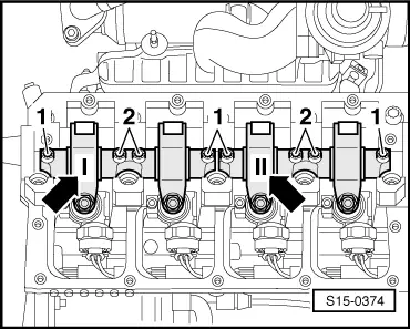
–  Place the clamping pad in the side slot of the unit injector.
  Note
If the unit injector is not perpendicular to the clamping pad the fixing screw may loosen and cause damage to the unit injector or cylinder head.
–  Align the unit injector as follows:
–  Screw the new fixing screw in the clamping pad until the unit injector can still easily be turned.
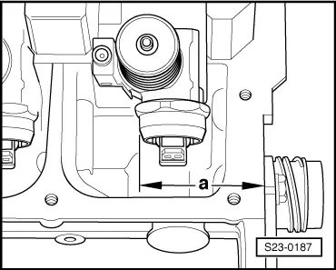
–  Set unit injector at a right angle to the bearing shell of the camshaft.
   
–  Using a caliper gauge, check dimension -a- from the outer side of the cylinder head to the cylinder surface of the unit injector.
  S23-0187
CylinderDimension -a-
1333,0 ± 0,8 mm
2245,0 ± 0,8 mm
3153,6 ± 0,8 mm
465,6 ± 0,8 mm

–  Adjust the unit injector as required, tighten the fixing screw using a torque of 12 Nm and then turn through a further 270° (3/4 turn). Tightening may occur in successive stages.
   
–  Mount valve-lever shaft and tighten up the new fixing screws as follows:
–  First tighten the inside -2- then both outside -1- screws by hand. In the same sequence tighten to 20 Nm and turn a further 90 ° (1/4 turn).
  S15-0374
–  Place a dial gauge on the adjusting screw of the unit injector.
  Note
Turn engine at hexagonal head of central screw at front end of the crankshaft, if necessary using counterholder -T10172- or using counterholder -MP1-216 (3036)- at camshaft sprocket.
–  Turn the crankshaft in the running direction of the engine until the roller of the valve lever is on the drive cam tip.
t  Roller side -arrow A- is on the highest point.
t  Dial gauge -arrow B- is on the lowest point.
–  Remove the dial gauge.
–  Turn the adjusting screw in the valve lever until one feels a significant resistance (the unit injector is against the stop).
  S23-0140
–  Turn the adjusting screw in the opposite direction from the stop by about 180°
–  Hold the adjusting screw in this position and tighten up the lock nut using a torque of 30 Nm
–  Fit the plug of the unit injector and install the cylinder head cover and the top toothed belt guard.
  N23-10092

Removing and installing the engine speed sender G28 (Superb II, Octavia II, Fabia II, Roomster) > < Removing