
Octavia Mk2
| Disassembling and assembling output shaft 5th/6th gear and reverse gear |
 Note
Note| t | If the output shaft or tapered-roller bearing is replaced, it is necessary to adjust the output shaft → Chapter. |
| t | Replace both tapered-roller bearings together. |

| 1 - | Clutch housing |
| 2 - | Washer |
| q | always 0.65 mm thick |
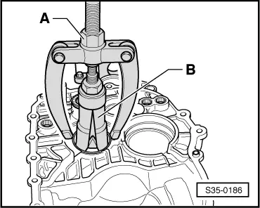
| 3 - | Outer ring/tapered-roller bearing |
| q | removing → Fig. |
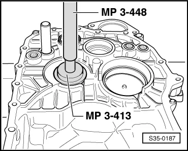
| q | installing → Fig. |
| 4 - | Inner ring/tapered-roller bearing |
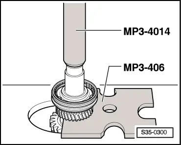
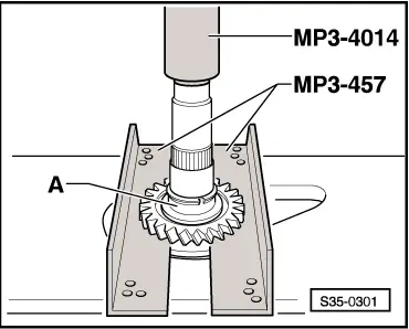
| q | remove → Fig. |
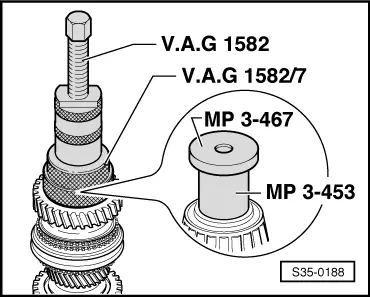
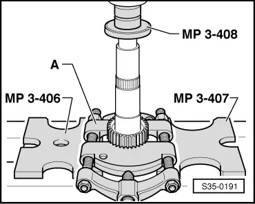
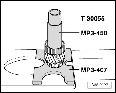
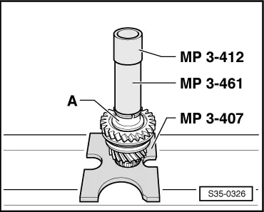
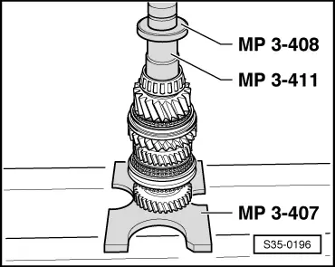
| q | pressing on → Fig. |
| 5 - | Output shaft |
| q | 5./6. and reverse gear |
| q | adjust → Chapter |
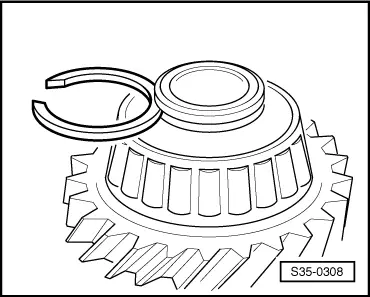
| 6 - | Reverse gear synchronizer body |
| q | remove → Fig. |
| q | Fitting position → Fig. |
| q | pressing on → Fig. |
| 7 - | Circlip |
| 8 - | Reverse gear sliding sleeve |
| q | with synchronizer ring |
| 9 - | Needle bearing |
| q | for reverse gear sliding gear |
| 10 - | Reverse gear sliding gear |
| 11 - | Bushing |
| q | pressing off with reverse gear sliding gear → Fig. |
| q | Fitting position: broad collar of bushing points to the reverse gear sliding gear |
| q | pressing on → Fig. |
| 12 - | Circlip |
| 13 - | Needle bearing |
| q | for 6th gear |
| 14 - | 6th gear sliding gear |
| 15 - | 6th gear synchronizer ring |
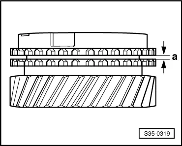
| q | check for wear → Fig. |
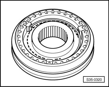
| 16 - | Sliding sleeve with 5th and 6th gear synchronizer body |
| q | after removing the circlip -Pos. 17- press off with the 6th gear sliding gear → Fig. |
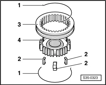
| q | disassembling → Fig. |
| q | Assembling sliding sleeve/synchronizer body → Fig. and → Fig. |
| q | pressing on → Fig. |
| 17 - | Circlip |
| 18 - | Needle bearing |
| q | for 5th gear |
| 19 - | 5th gear synchronizer ring |
| q | check for wear → Fig. |
| 20 - | 5th gear sliding gear |
| 21 - | Inner ring/tapered-roller bearing |
| q | remove → Fig. |
| q | pressing on → Fig. |
| 22 - | Circlip |
| q | determine → Fig. when replacing the tapered-roller bearing -Pos. 21- and the output shaft -Pos. 5- |
| 23 - | Outer ring/tapered-roller bearing |
| q | removing → Fig. |
| q | installing → Fig. |
| 24 - | Adjusting washer |
| q | Determine thickness → Chapter |
| 25 - | Gearbox housing |
| 26 - | Spring |
| q | Fitting position → Fig. |
| 27 - | Sliding sleeve |
| 28 - | Synchronizer body |
| 29 - | Arresters (3 pieces) |
| q | Fitting position → Fig. |
|
|
|
|
|
|
|
|
|
|
|
|
|
|
|
|
|
|
|
|
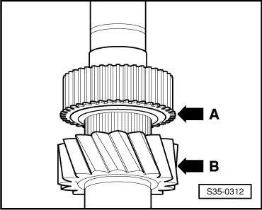
| Clearance -a- | Fitting dimension | Wear limit |
| 5th and 6th gear | 1.0 … 1.7 mm | 0.5 mm |
|
|
|
|
|
|
|
|
|
|
| Thickness (mm) | Part number |
| 1,79 | 02M 311 187 G |
| 1,83 | 02M 311 187 F |
| 1,86 | 02M 311 187 E |
| 1,89 | 02M 311 187 D |
| 1,92 | 02M 311 187 C |
| 1,95 | 02M 311 187 B |
| 1,98 | 02M 311 187 A |
|
|
|
|
|
|