skoda Workshop Repair Guides

Skoda Workshop Service and Repair Manuals

Installing the gearbox > < Removing and installing gearbox (Octavia II, Superb II, Yeti)
Removing the gearbox
–  Shift selector lever into position „P“.
  Note
Do not take out ignition key.
–  Remove engine cover → engine; Rep. gr.10.
–  Remove air filter → Engine; Rep. gr.24 or → Engine; Rep. gr.23.
–  Remove battery and battery tray → Electrical System; Rep. gr.27.
Vehicles Octavia II and Yeti
–  Remove the cooling water tank cover → Body Work; Rep. gr.66.
Continued for all vehicles
   
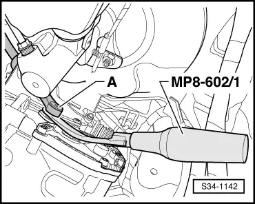
–  Expose the selector lever control cable -A- from the gearbox shift lever with the removal tool for the inner lining of the door panel-MP8-602/1-.
  S34-1142
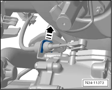
–  Remove the lock washer -arrow- of the selector lever control cable, the selector lever control cable must be left in the fitting position.
  Note
t  The lock washer -1- of the selector lever control cable must always be replaced → Electronic Catalogue of Original Parts.
t  Do not bend or buckle selector lever control cable.
t  Do not press the selector lever control cable out of the cable support towards the rear. The selector lever control cable is only guided out of the cable support when removing the gearshift mechanism.
  N34-11373
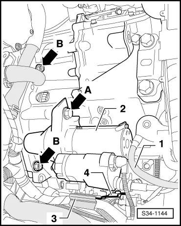
–  Remove the earth lead -1- from the fixing screw of the gearbox console.
–  Remove plug and cable from starter → Electrical System; Rep. gr.27.
–  Unscrew screw -arrow°A- from starter.
  Note
Unscrew the second fixing screw from the starter (not visible in the illustration) and remove starter -2-.
–  Unscrew the connecting screws -arrows B- at engine and gearbox. To this end, use if necessary the socket insert -T10035-.
–  Disconnect the cable connection -3- from the holder with attached electrical cables -4- and tie up.
–  Remove the holder -4- from the gearbox.
  S34-1144
One of the screws is located in the starter opening (only on certain types of engines e.g. on 1.4 engines).
–  Screw out this screw.
  Caution
Under no circumstances must the plug contacts in the plug of the gearbox be touched with the hands, because the control unit can be destroyed through static discharge as well as the mechatronics.
–  Grab with the hand (without gloves) at the mass, so that it discharges electrostatically.
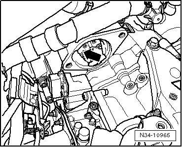
  N34-10965
–  Unlock the cap of the plug on the mechatronics by pulling in -direction of arrow- and disconnect the plug.
Vehicles Octavia II and Yeti
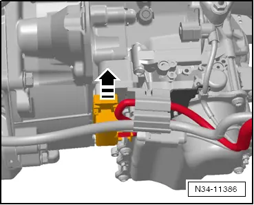
  N34-11386
–  Fit supporting device -T30099-.
–  Slightly pre-tension the engine/gearbox unit via the spindles, do not raise.
Vehicles Superb II
–  Remove the filling pieces from both upper edges of the wings.
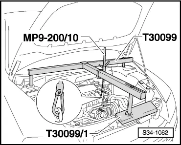
  S34-1082
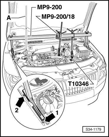
–  Tighten the holder -T10346- on the rear of the three location holes for the battery tray.
–  To do so, use a collar screw M6 or one of the fixing screws for the battery tray.
–  Position the supporting device -MP9-200 (10-222 A)- behind the pressurized gas strut -A- for the front flap.
–  The feet of the supporting device must be placed as shown in the illustration, behind the screw -arrow 1- and sideways up to the screw -arrow 2- on the wheelhouse frame side rail at the top.
–  Connect the holder -T10346- with the supporting device.
–  Hook the second spindle into the front left engine lifting eye.
–  Slightly take up the weight of the engine/gearbox unit via the spindle, do not raise.
Vehicles Yeti
  S34-1179
–  Fit supporting device -T30099-.
–  Slightly pre-tension the engine/gearbox assembly via the spindle (do not raise) (use only one spindle of the supporting device on 1.2/77 kW engine).
Only on vehicles with rigid shaft (up to 11.08)
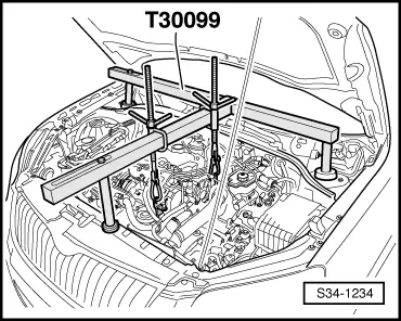
  S34-1234
–  Actuate the brake pedal and slacken the left drive shaft bolt -arrow- (2nd mechanic).
–  Loosen the wheel bolts on front left and front right.
–  Raise vehicle.
Continued for all vehicles
–  Remove wheels at the front.
  Note
After slackening the drive shaft bolt -arrow- the vehicle must no longer be lowered onto the floor.
–  Remove the sound dampening system → Body Work; Rep. gr.50.
–  Remove the front left wheelhouse liner → Body Work; Rep. gr.66.
–  Remove the charge air hose from the bottom left charge air cooler and the charge air pipe → Engine; Rep. gr.21.
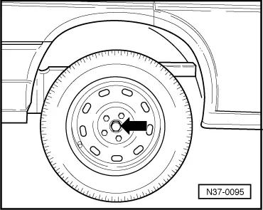
  N37-0095
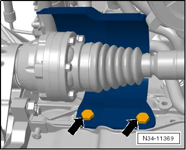
–  Remove the protective cap for right drive shaft from the engine -arrows-.
  N34-11369
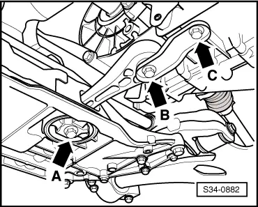
–  Remove pendulum support, to do so screw out screws -arrows A, B and C-.
–  Separate exhaust system at the double clamp and remove bracket for the exhaust system from the assembly carrier → Engine; Rep. gr.21.
–  Tie up pre-exhaust pipe.
  S34-0882
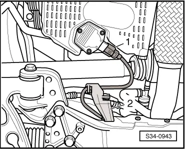
–  Disconnect plug -1- at the oil level and oil temperature sender -G266-.
–  Unclip the wiring loom from the holder -2-.
–  Remove coupling rod from anti-roll bar.
–  Fix the assembly carrier before removing → Chassis; Rep. gr.40.
–  Remove the assembly carrier with console without steering gear, left track control arm and coupling rod → Chassis; Rep. gr.40.
Only on vehicles with rigid shaft (up to 11.08)
  S34-0943
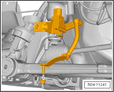
–  If present, remove front left vehicle level sensor -G78-.
  N34-11241
–  Unscrew the nuts -arrows- from the steering joint to the right track control arm.
–  Unhook the steering joints from the track control arms.
–  Press off the left and right drive shaft from the rigid shafts of the gearbox e.g with wedge -T10161- or tyre iron → Chassis; Rep. gr.40.
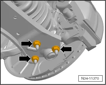
–  Remove left drive shaft → Chassis; Rep. gr.40.
  N34-11370
–  Tie up the drive shaft as far as possible. Avoid damaging the paintwork on the drive shaft during this operation.
Only on vehicles with flange shaft (as of 11.08)
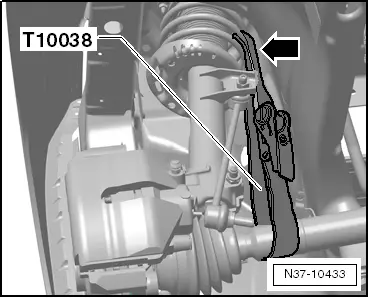
  N37-10433
–  If present, remove front left vehicle level sensor -G78-.
–  Remove drive shafts from flange shafts → Chassis; Rep. gr.40.
  N34-11241
–  Tie up the drive shaft as far as possible. Avoid damaging the paintwork on the drive shaft during this operation.
Continued for vehicles with 1.2 and 1.4 engines
On the 1.4 engine separate the front exhaust system, the exhaust system must not be separated on the 1.2 engine.
  N37-10433
–  Unscrew the bottom engine/gearbox connecting screws -arrows-.
Continued for all vehicles
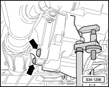
  S34-1256
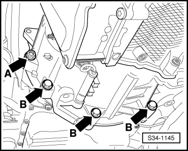
–  Unscrew bottom connecting screws -arrow°A- and -arrow°B- from engine/gearbox.
  S34-1145
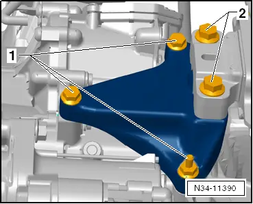
Slacken the screws -1- of the gearbox console by approx. one turn and screw out the screws -2-.
  N34-11390
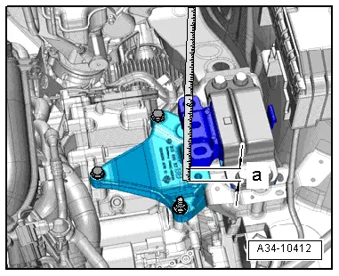
–  Then lower the engine and gearbox via the spindles of the supporting device -MP9-200 (10-222 A)- as far as necessary so that there is a gap of dimension -a- between the gearbox console and the gearbox mount.
l  Dimension -a- = 60 … 70 mm.
  A34-10412
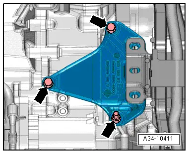
–  Screw out screws -arrows- and remove gearbox console.
  A34-10411
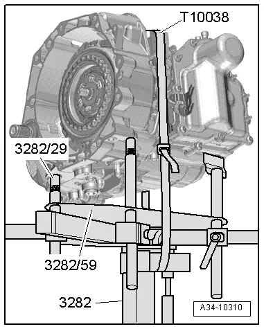
For the removal of the gearbox 0AM the gearbox mount -3282- is aligned with the adjusting plate -3282/59- and placed on the engine/gearbox jack -V.A.G 1383 A-.
–  Align arms of the gearbox mount to match the holes in the adjusting plate -3282/59-.
–  Screw in the mounting elements as shown on adjusting plate -3282/59-.
–  Position the engine/gearbox jack -V.A.G 1383 A- below the vehicle.
l  The arrow symbol on the adjusting plate -3282/59- points in the direction of travel.
–  Align the gearbox mount -3282- parallel to the gearbox.
–  Screw the bolt -3282/29- into the gearbox.
–  Place both remaining mounting elements on the gearbox as shown. To do so, place the panel of the drift under the gearbox housing and not under the mechatronics.
–  Secure the gearbox with the tensioning strap -T10038-.
–  Position the gearbox by lifting the engine/gearbox jack -V.A.G 1383 A- from the bottom.
  A34-10310
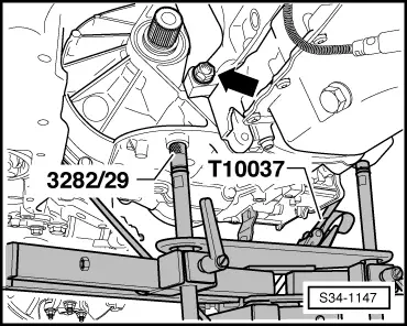
–  Unscrew the last connecting screw -arrow B- at engine and gearbox.
–  Press the gearbox out of the sleeves.
–  Carefully separate the gearbox from the engine and carefully lower.
–  When lowering the gearbox, guide the selector lever control cable out of the cable support.
  Note
t  Observe all lines and coolant hoses when lowering the gearbox.
t  Do not bend or buckle selector lever control cable.
  S34-1147
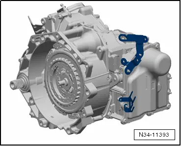
In some cases, the brackets are located at the front of the gearbox.
  Note
If a »new« gearbox must be installed, the brackets must be fitted to the »new« gearbox.
Transporting the gearbox and secure to the assembly support → Chapter.
Installing the gearbox → Chapter.
  N34-11393

Installing the gearbox > < Removing and installing gearbox (Octavia II, Superb II, Yeti)