skoda Workshop Repair Guides

Skoda Workshop Service and Repair Manuals

Connection diagram for vacuum hoses > < Removing and installing exhaust gas turbocharger
Removing and installing exhaust gas temperature sender 1G235 (temperature sender upstream turbochargerG507)
Removing and installing exhaust gas temperature sender 1 -G235- (temperature sender upstream turbocharger -G507-)
Removing
   
–  Disconnect plug connection -3- for exhaust gas temperature sender 1 -G235- (temperature sender upstream turbocharger -G507-) and place down the electrical line.
On vehicles with four-wheel drive
–  Remove propshaft → Gearbox; Rep. gr.39.
Continued for all vehicles
  A23-10003
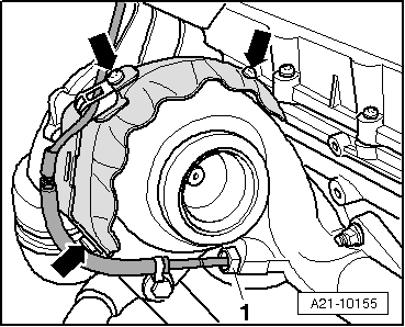
–  Unscrew exhaust gas temperature sender 1 -G235- (temperature sender upstream turbocharger -G507-) -1- from the exhaust manifold.
Install
Installation is performed in the reverse order, pay attention to the following points:
  Note
t  The thread of the new temperature sender must be coated with assembly paste.
t  Grease only the thread with hot bolt paste -G 052 112 A3- for re-used temperature sender.
t  All cable straps should be fastened again in the same place when installing.
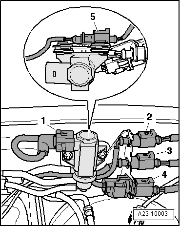
Fitting position of the exhaust gas temperature sender 1 -G235- (temperature sender upstream turbocharger -G507 -):
  A21-10155
l  The dimension -a- should not be less than 0.5 mm.
t  Tightening torque: 45 Nm.
  N21-10161

Connection diagram for vacuum hoses > < Removing and installing exhaust gas turbocharger