skoda Workshop Repair Guides

Skoda Workshop Service and Repair Manuals

Removing and installing exhaust gas temperature sender 1G235 (temperature sender upstream turbochargerG507) > < Exhaust gas turbocharger with component parts - Summary of components
Removing and installing exhaust gas turbocharger
Special tools and workshop equipment required
t  Pliers for spring strap clamps
t  Key -T10461-
Removing
  Caution
In case of mechanical damage to the exhaust gas turbocharger, e.g. damage of the compressor wheel, it is not sufficient to only replace the exhaust gas turbocharger. In order to prevent consequential damage to the engine, perform the following tasks:
t  Clean all oil lines.
t  Change engine oil and oil filter.
t  Check air filter housing, air filter element and charge air pipes as well as charge air hoses for soiling.
t  Check all the air guides and the charge air cooler for foreign bodies.
If foreign bodies are detected in the charge air system, the complete charge-air routing must be cleaned and if necessary the charge air cooler must also be replaced.
  Note
t  Observe rules for cleanliness → Chapter.
t  Observe general instructions for charge-air system → Chapter.
–  Remove pre-exhaust pipe with diesel particle filter → Chapter.
–  Remove air filter housing with air mass meter -G70- and intake hose → Chapter.
   
–  Remove the heat shield collar and disconnect the plug -1- on the position sender for charge pressure regulator -G581-.
–  Remove vacuum hose -2- from vacuum setting element of exhaust turbocharger.
–  Disconnect vacuum hose -3-.
  A21-10338
–  Disconnect plug connection -3- for exhaust gas temperature sender 1 -G235- (temperature sender upstream turbocharger -G507-) and place down the electrical line.
For the vehicles Octavia II, Superb II
–  Remove fan shroud with radiator fans → Chapter.
For the vehicles Superb II up to 10.08
  A23-10003
–  Unscrew screws -2 and 5- as well as screws -arrows-.
For the vehicles Octavia II, Superb II as of 11.08, Yeti
  A19-10641
–  Screw out screws -arrows- and screw -5-.
Continued for all vehicles
–  Release screw clamp -3- and remove left charge air pipe.
  A21-10493
–  Slacken the union nut -3- and unscrew the oil feed line from the connection on the exhaust turbocharger. At the same time counterhold the hexagon of the connection fitting using the wrench -T10461-.
  A15-10634
–  Release nuts -1- and remove heat shield from exhaust manifold.
  Caution
Pay attention that the bellows of the connection pipe is not bent and therefore is not overstretched. There is a risk of crack formation.
–  Release nuts -2- and screws -3- and remove exhaust gas recirculation pipe.
  Caution
The exhaust gas temperature sender 1 -G235- (temperature sender upstream turbocharger -G507-) covers the top bolted connection of the support for exhaust turbocharger and must not be bent. For this reason it must be removed.
–  Remove exhaust gas temperature sender 1 -G235- (temperature sender upstream turbocharger -G507-) → Chapter.
On vehicles with four-wheel drive
–  Remove right flange shaft from angle gearbox → Gearbox; Rep. gr.39 → Chapter „Replacing gasket ring for right flange shaft“.
Continued for all vehicles
  A21-10153
–  Release screws -1 and 2- and hollow screw -3-.
–  Remove support for exhaust turbocharger with oil return line.
  A21-10088
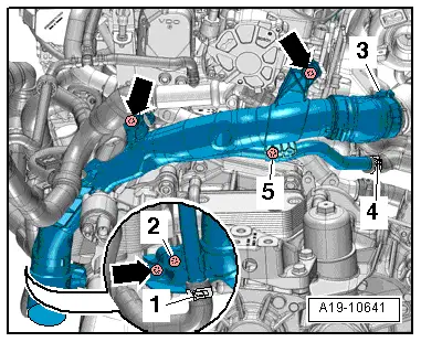
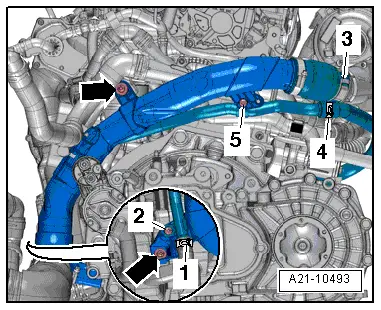
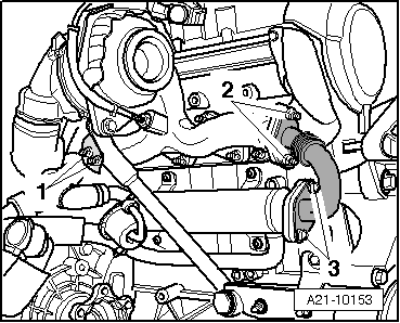
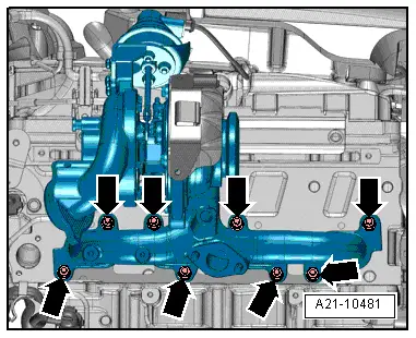
–  Unscrew nuts -arrows- and remove the exhaust gas turbocharger with exhaust manifold from the cylinder head.
–  Remove the exhaust turbocharger with exhaust manifold downwards, to do so slightly push the engine gearbox assembly to the front.
Install
Installation is performed in the reverse order, pay attention to the following points:
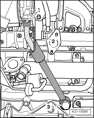
  Caution
Before installing, check whether the bellows of the oil return pipe is not bent or overstretched. If this is the case, microcracks might occur which can result in leaks. Replace damaged oil return pipe or support for exhaust gas turbocharger.
  Note
t  Replace the gaskets, the sealing rings and the self-locking nuts.
t  
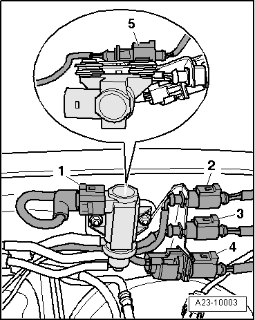
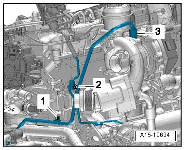
Fill exhaust turbocharger with engine oil through the connection fitting of the oil feed line.
t  Remove oil and grease from the charge air pipes and hoses and from their connections before installing.
t  Observe the assembly instruction for hose connections with push-fit couplings → Chapter.
t  Secure all hose connections with screw clamps.
t  Only install approved clamps for securing the hose connections → Electronic Catalogue of Original Parts.
t  Tightening torques: → Chapter.
–  Checking the oil level:
t  → BookletOctavia II.
t  → BookletSuperb II.
t  → BookletYeti.
  Note
After installing the turbocharger, run engine at idling speed for about 1 minute to ensure that oil is supplied to the turbocharger.
  A21-10481

Removing and installing exhaust gas temperature sender 1G235 (temperature sender upstream turbochargerG507) > < Exhaust gas turbocharger with component parts - Summary of components