skoda Workshop Repair Guides

Skoda Superb Service and Repair Manuals

Repairing Valve Gear > < Removing and installing the two-mass flywheel
Removing
Removing
Requirements
l  Engine temperature should not exceed 35 °C, because the cylinder head could be twisted when slackening the screws.
l  The pistons must not be positioned at top dead centre.
–  Switch off ignition and withdraw ignition key.
–  Remove top engine cover.
–  Remove noise insulation → Body Work → Rep. Gr.50.
–  Remove the lock carrier with component parts → Body work → Rep. Gr.50.
  WARNING
Hot steam or hot coolant may escape when the compensation bottle is opened. Cover the cap with cloths and open carefully.
–  Position the catch pan, e.g. -VAS 6208 - under the engine.
–  Drain coolant → Chapter.
   
–  Unplug connector -1- from intake manifold pressure sender -G71- with intake temperature sender -G72-.
–  Unscrew screw -2- and remove air guide to induction pipe -arrows-.
–  Detach the vacuum line to the brake servo unit at the bulkhead.
–  Unplug connector from air mass meter -G70- and remove air filter → Chapter.
–  Loosen hose clamp and detach air guide hose to turbocharger.
  A10-1035
–  Disconnect plug -1- from exhaust gas recirculation valve -N18- with exhaust gas recirculation potentiometer -G212- and EGR control motor -V338- and plug -2- from intake manifold flap motor -V157-.
–  Detach coolant hoses from radiator for exhaust gas recirculation.
–  Detach vacuum hose from vacuum setting element for charge pressure control at turbocharger.
  Note
The decoupling element in the pre-exhaust pipe should not be bent by more than 10° - danger of damaging it.
  A23-10018
–  Unscrew nuts at exhaust turbocharger flange -arrows-, remove hanger for exhaust pipe, slacken screws of double clamp on the exhaust pipe and push the complete front exhaust pipe to the rear → Chapter.
  A10-0358
–  Remove air guide hose from exhaust turbocharger, to do so pull retaining clip -arrow-.
  A21-10022
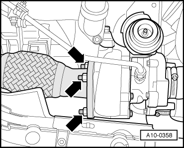
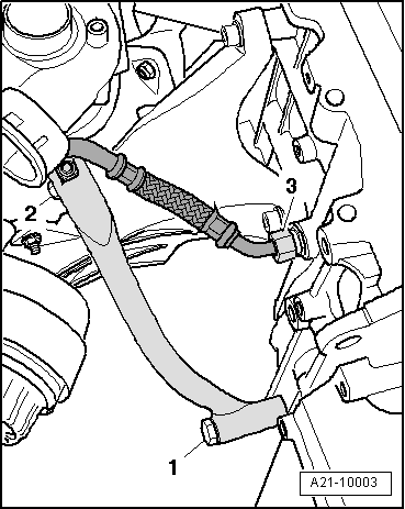
–  Release screws -2 and 3- and remove support for turbocharger.
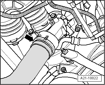
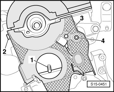
–  Remove the oil return line -3- from the cylinder block.
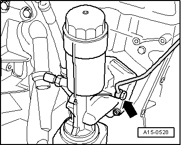
–  Remove fuel filter with bracket and separate fuel feed and return-flow line from the tandem pump → Chapter.
–  Before removing the cylinder head, extract the fuel from the tandem pump using the extraction system, e.g. -VAS 5226- → Chapter.
–  Detach hoses and remove top coolant pipe → Chapter.
–  Detach coolant hoses from connection fitting of cylinder head → Chapter.
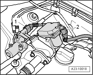
–  Unplug plug for glow plugs, central screw for unit injectors and plug for coolant temeprature sender -G62- → Chapter.
  A21-10003
–  Detach the oil feed line for the exhaust turbocharger -arrow- from the oil filter holder.
–  Slacken timing belt tensioning pulley and take timing belt off camshaft sprocket → Chapter.
–  Remove toothed belt sprocket and hub of camshaft → Chapter.
–  Remove toothed belt tensioning pulley → Chapter.
  A15-0528
–  Remove screws -1...4-.
–  Remove intake manifold with exhaust gas recirculation radiator → Chapter.
–  Remove cylinder head cover → Chapter.
  S15-0451
–  Follow the specified order for loosening cylinder head bolts.
–  Remove cylinder head and place down on a soft surface with the sealing surface to the top.
  Note
t  Engines with ceramic glow plugs: cylinder head with installed ceramic glow plugs must never be put down onto the sealing surface, otherwise the ceramic glow plugs can protrude slightly and may be destroyed.
t  Handling the ceramic pencil type glow plugs → Chapter.
t  Removing and installing ceramic glow plugs → Chapter.
  S15-0297

Repairing Valve Gear > < Removing and installing the two-mass flywheel