| –
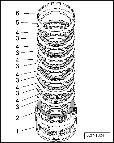
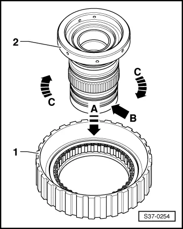
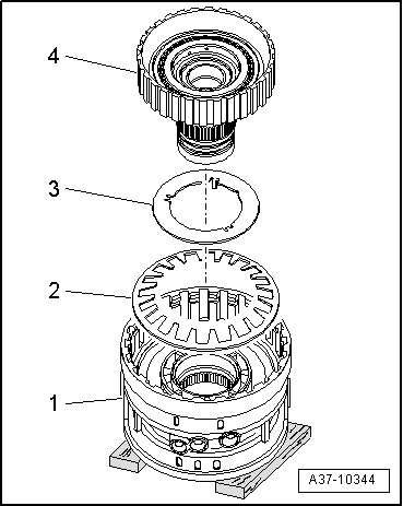
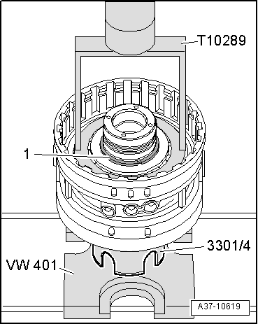
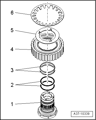
| Put cylinder “D/G”-pos. 1- onto 2 squared timbers of approx. 40 mm. |
| l
| The cylinder “D” points upwards. |
| –
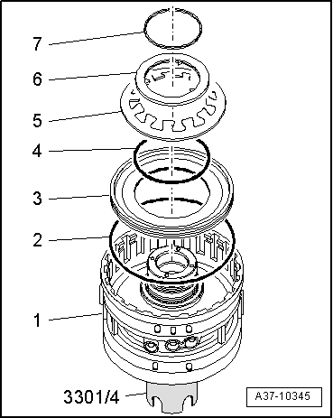
| Insert the disc spring -2- and the retaining washer -3- into cylinder “D/G”. |
| l
| The pegs on the retaining washer point to the cylinder “D/G” and must be inserted into the recesses of the cylinder “D/G” |
| –
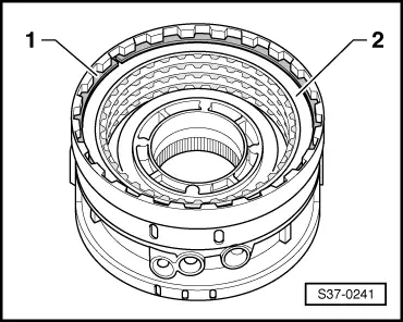
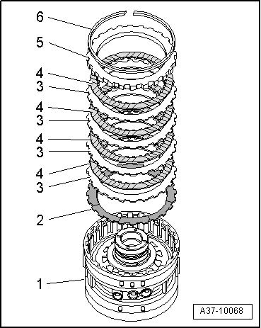
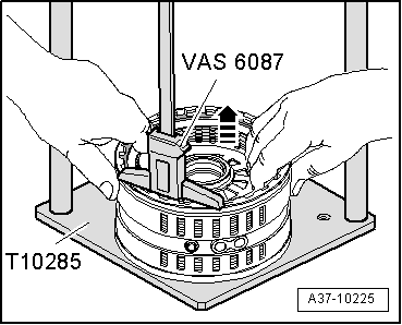
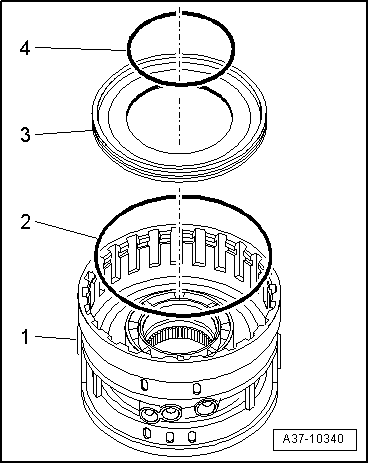
| Take hold of the free wheel -4- in such a way that the free wheel inner race can no longer slip out. |
| –
| Then insert the free wheel inner race, to do so press the serration of the free wheel inner race into the serration of the cylinder “D/G”. |

Note | t
| If the free wheel with free wheel cage slips to the bottom when inserting the free wheel inner race, it is positioned again onto the free wheel inner race. |
| t
| After insertion, the free wheel with free wheel cage must only have a low axial play. |
|
|
|

 WARNING
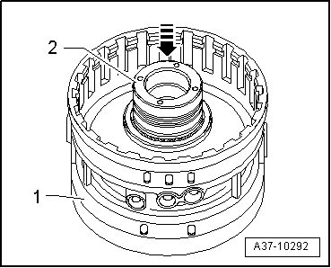
 Caution