skoda Workshop Repair Guides

Skoda Workshop Service and Repair Manuals

Disassembling and assembling gearbox - Summary of assembly procedure > < Removing and installing shift mechanism
Install
Install
If the ball bearing for the drive shaft, the drive shaft or the gearbox housing have been replaced, first the thickness of the circlip for the drive shaft must be determined again → Chapter.
   
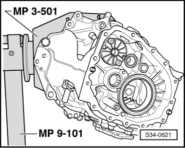
–  Swivel the gearbox housing into the indicated position.
–  The mentioned components can then better inserted.
  S34-0621
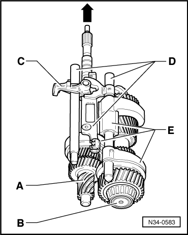
–  Assemble drive shaft -A-, secondary shaft (output shaft) -B-, guide shaft -C-, gear shift rods -D- with gearshift shaft and shift forks -E-.
–  Insert these components together in the gearbox housing.
  Note
The guide shaft -C- and the gearshift shaft can if necessary also be inserted subsequently → Anchor, Fig. N34-0585 and V34-2120.
  N34-0583
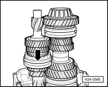
–  Swivel the gearbox housing and then engage the 3rd gear -direction of arrow-.
  N34-0585
–  Insert guide shaft -A-.
–  Position gearshift shaft -B- sideways onto the location hole in the gearbox housing and assemble together with the lifting eye.
–  Then carefully swivel the drive shaft into the -direction of arrow-.
  V34-2120
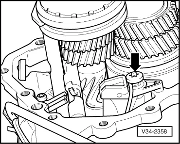
–  Insert detent segment and tighten -arrow-.
  V34-2358
–  Screw in screws for guide shaft -arrows-.
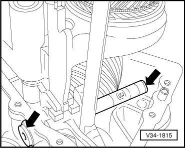
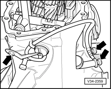
–  Replace O-ring for reversing lights switch -F4-.
  V34-1815
–  Carefully insert the reversing lights switch -F4- and tighten -arrows-.
  V34-2359
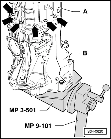
–  Check whether the dowel sleeves for the gearbox cover -A- are present in the gearbox housing -B-.
–  Screw gearbox cover -A- onto gearbox housing -B--arrows-.
  S34-0620
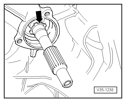
–  Install the rear circlip -arrow- for the ball bearing of the drive shaft.
–  Push the ball bearing onto the drive shaft.
Fitting position: The closed side of the ball cage points to the gearbox housing.
  V35-1238
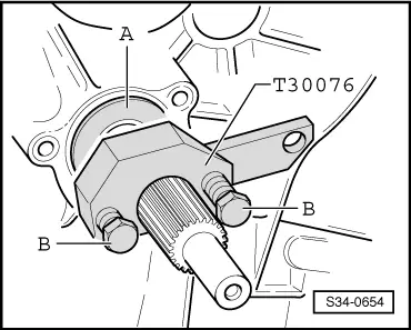
–  Press in ball bearing:
Push the thrust washer -A- of the press-in tool -3235- onto the drive shaft.
Now fit on the press-in tool behind the serration for the clutch disc. Pretension the screws -B-. The screws are supported in the countersinks of the thrust washer -A-.
Press in the ball bearing by alternatively tightening the screws (1/2 turn) up to the stop.
  S34-0654
–  Now install the front circlip -D- for the ball bearing of the drive shaft.
–  Position the disc spring -C-.
Fitting position: The curved side points to the guide bushing -B-.
  Note
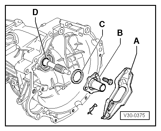
Before sliding on the guide bushing for protection of the gasket ring pull the shrink hose over the serration of the drive shaft.
–  Install guide bushing -B- for release bearing.
–  Install clutch release lever -A- together with release bearing.
  V30-0375

Disassembling and assembling gearbox - Summary of assembly procedure > < Removing and installing shift mechanism