
Yeti
| Summary of components |
 Note
Note| If considerable quantities of metal swarf or abrasion is found when carrying out engine repairs, this can be subject to damage to the crankshaft and conrod bearings. In order to avoid consequential damage, after the repair perform the following tasks: |
| – | Carefully clean the oil galleries. |
| – | Replace oil spray jets. |
| – | Replace engine oil cooler. |
| – | Replace oil filter. |
| t | Before removing the crankshaft, ensure a suitable place is available for placing it down so that the sensor rotor → Item does not rest on anything or get damaged. |
| t | Secure the engine with engine mount -MP 1-202- on the assembly stand -MP 9-101- before performing assembly work. |
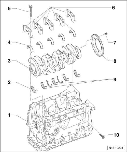
| 1 - | Cylinder block |
| 2 - | Bearing shells for cylinder block |
| q | with lubricating groove |
| q | do not mix up used bearing shells (mark) |
| q | Identification → Chapter |
| 3 - | Crankshaft |
| q | Axial play when new: 0,07…0,23 mm |
| Wear limit: 0,30 mm |
| q | Crankshaft bearing pins: Ø 58.00 mm |
| q | Conrod bearing: Ø 47.80 mm |
| 4 - | Bearing shell for bearing cap |
| q | without lubricating groove |
| q | do not mix up used bearing shells (mark) |
| q | Identification → Chapter |
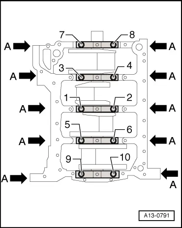
| 5 - | Screw |
| q | replace |
| q | order of tightening → Fig. |
| 6 - | Bearing caps |
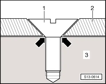
| q | Bearing cap 1: belt pulley side |
| q | retaining lugs of the bearing shells of the cylinder block/bearing cap must be on top of one another |
| 7 - | 10 Nm + torque a further 90° (1/4 turn) |
| q | replace |
| 8 - | Rotor |
| q | for engine speed sender -G28- |
| q | replace sensor rotor each time the bolts are slackened |
| q | assembly only possible in one position -holes offset- |
| q | removing and installing → Fig. |
| 9 - | Thrust washers |
| q | for bearing 3 |
| 10 - | Screw |
| q | replace |
| q | order of tightening → Fig. |
|
|