
Impreza Outback Sport AWD F4-2.5L SOHC (2002)
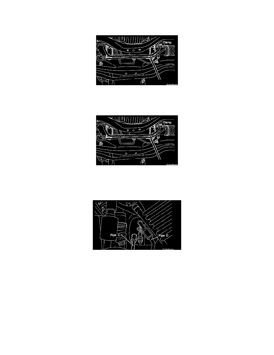
CAUTION: Be careful not to damage these pipes.
NOTE: Disconnect the upper pipe D first, and lower pipe C second.
13. Remove the clamp bolts securing gearbox to the crossmember, and remove the gearbox.
B: INSTALLATION
1. Insert the gearbox into the crossmember, being careful not to damage gearbox boot.
2. Tighten the gearbox to the crossmember bracket via clamp with bolt to the specified torque.
Tightening torque: 59 Nm (6.0 kgf-m, 43 ft. lbs.)
3. Install the four pipes on the gearbox.
1. Connect the pipes A and B to the four pipe joints of gearbox. Connect the upper pipe B first, and lower pipe A.
Tightening torque: 13 Nm (1.3 kgf-m, 9.4 ft. lbs.)
2. Connect the pipes C and D to the gearbox. Connect the upper pipe D first, and lower pipe C second.
Tightening torque: 15 Nm (1.5 kgf-m, 10.8 ft. lbs.)
4. Install the universal joint.
5. Connect the tie-rod end and knuckle arm, and tighten with castle nut. Fit the cotter pin into the nut and bend the pin to lock.
Castle nut tightening torque: Tighten to 27.0 Nm (2.75 kgf-m, 19.9 ft. lbs.), and tighten further within 60° until cotter pin hole is aligned with a
slot in the nut.