
Swift GA L4-1298cc 1.3L SOHC MFI (2001)
1. Disconnect negative cable from battery.
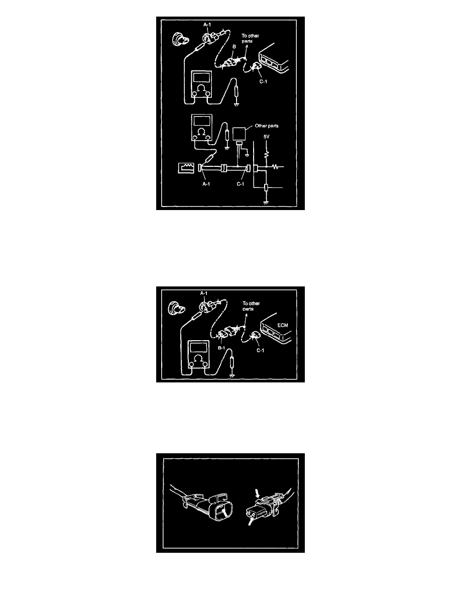
2. Disconnect connectors at both ends of the circuit to be checked.
NOTE: If the circuit to be checked is connected to other parts, disconnect all connectors of those parts. Otherwise, diagnosis will be misled.
3. Measure resistance between terminal at one end of circuit (A-1 terminal in figure) and body ground. If continuity is indicated, it means that there is
a short to ground between terminals A-1 and C-1 of the circuit.
4. Disconnect the connector included in circuit (connector B) and measure resistance between terminal A-1 and body ground. If continuity is
indicated, it means that the circuit is shorted to the ground between terminals A-1 and B-1.
Intermittents and Poor Connection
Most intermittents are caused by faulty electrical connections or wiring, although a sticking relay or solenoid can occasionally be at fault. When checking
it for proper connection, perform careful check of suspect circuits for:
-
Poor mating of connector halves, or terminals not fully seated in the connector body (backed out).
-
Dirt or corrosion on the terminals. The terminals must be clean and free of any foreign material which could impede proper terminal contact.