
XL-7 4WD V6-3.6L (2008)
Drive/Propeller Shaft: Procedures
Driveline System Balance Adjustment (Using Eva)
Driveline System Balance Adjustment (Using EVA)
This procedure is designed to fine-tune the balance of a propeller shaft while it is mounted in the vehicle. Small amounts of residual imbalance which
could be present in other related driveline system components could be compensated for as a result of performing this procedure. The end result of
properly fine-tuning a propeller shaft balance may be either a significant reduction or an elimination of a vibration disturbance that is related to the
first order rotation of a propeller shaft.
Fine-tuning the balance of a propeller shaft can aid in achieving a more balanced total driveline system.
NOTE:
The runout of the propeller shaft to be balanced and the runout of the components that the propeller shaft mates to must be within tolerances before an
attempt should be made to perform this procedure.
If J 38792-A Electronic Vibration Analyzer (EVA) 2 is available, use the following procedure, Adjustment Procedure Using EVA. If the EVA 2 is not
available, use the second procedure, Adjustment Procedure Without EVA.
Adjustment Procedure Using EVA
Special Tool
J 38792-A Electronic Vibration Analyzer (EVA) 2
J 38792-20 20-Foot Timing Light Power Cord Extension
J 38792-25 Inductive Pickup Timing Light, or equivalent
J 38792-27 6-Foot EVA Power Cord Extension
CAUTION:
Do not depress the brake pedal with the brake rotors and/or the brake drums removed, or with the brake calipers repositioned away from
the brake rotors, or damage to the brake system may result.
1. Raise and support the vehicle; ensure that the drive axle or axles are supported at ride height - vehicle body supported by suspension components.
2. With the tire and wheel assemblies, and the brake rotors and/or brake drums removed from the drive axle, or axles, start the engine and turn OFF
all engine accessories.
3. Place the transmission in forward gear.
4. Run the vehicle at the speed which causes the most vibration in the propeller shaft; observe which end of the propeller shaft exhibits the greatest
amount of vibration disturbance.
5. Turn the engine OFF to slow and stop the rotation of the propeller shaft.
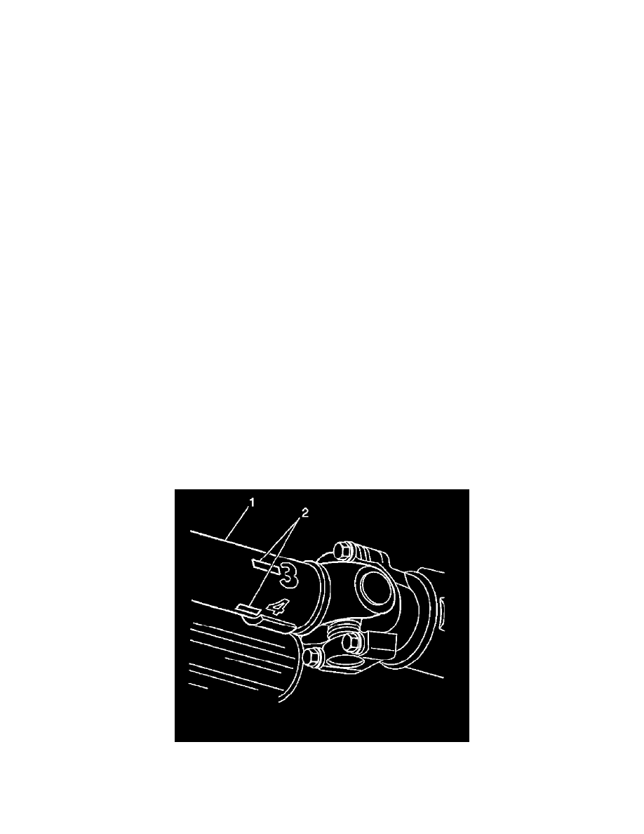
6. Mark the circumference of the propeller shaft (1) to be balanced at four points 90 degrees apart (2), nearest the end that exhibited the greatest
amount of vibration. Number the marks 1 through 4.
7. Install the J 38792-A, the J 38792-27, the J 38792-25, or equivalent, and the J 38792-20 to the vehicle.
8. Connect the clip of the J 38792-25, or equivalent, onto the trigger wire of the J 38792-A.