
XL-7 4WD V6-3.6L (2008)
9. Mount the J 38792-A vibration sensor to the bottom of the driveline component nearest to the end of the propeller shaft that exhibited the greatest
amount of vibration.
Ensure that the side of the sensor marked UP faces upward and that the sensor is positioned as close to horizontal as possible.
10. Plug the vibration sensor cord into Input A of the J 38792-A. Input B is not used with the strobe function.
11. Run the vehicle at the speed which causes the most vibration in the propeller shaft; observe the frequency readings displayed on the J 38792-A.
NOTE:
Do NOT continue with fine-tuning the balance of a propeller shaft if the dominant frequency displayed is not related to the first-order rotational
speed of the propeller shaft.
12. Verify that the dominant frequency displayed on the J 38792-A matches the recorded frequency of the vibration concern.
13. Record the amplitude reading of the dominant frequency displayed.
14. Using the strobe function of the J 38792-A, select the correct filter range to use for the balance adjustment, so that the dominant frequency would
be near the middle of the filter range. Use the full range filter only as a last resort if one of the specific range filters will not cover the frequency
adequately.
15. The J 38792-A display will show the dominant frequency, the amplitude and the selected filter range.
16. Aim the J 38792-25, or equivalent, at the marks placed on the propeller shaft. When activated, the strobe effect will appear to freeze the marks
placed on the rotating propeller shaft. Record which of the numbered marks appears to be at the bottom of the propeller shaft, or the 6 o'clock
position. This position identifies the light spot of the propeller shaft.
17. Turn the engine OFF to slow and stop the rotation of the propeller shaft.
18. Install a band-type hose clamp as a weight, with the head of the clamp directly on the light spot.
19. Run the vehicle at the speed which causes the most vibration in the propeller shaft.
20. Using the J 38792-25, or equivalent, observe the positioning of the marks placed on the propeller shaft.
21. If the marks on the propeller shaft now appear to move erratically, compare the current amplitude of the vibration frequency to the original
amplitude recorded previously. If the amplitude has decreased from the amplitude recorded, the balance achieved may be sufficient and the vehicle
should be road tested to determine the effect on the vibration concern.
22. If the clamp head over the original light spot, is now near the top of the propeller shaft, within 180 degrees - near or below the 12 o'clock position
- of the original position at the bottom of the propeller shaft - 6 o'clock position - the position of the weight needs adjusting. Perform the following
steps:
a. Move the position of the clamp head toward the 6 o'clock position.
b. Using the J 38792-25, or equivalent, recheck the positioning of the propeller shaft marks.
c. If necessary, continue to move the position of the clamp head toward the 6 o'clock position and recheck progress until an improvement in
balance is achieved.
23. If the clamp head over the original light spot, is still positioned at the bottom of the propeller shaft - 6 o'clock position - additional weight is
required. Perform the following steps:
a. Add a second clamp to the propeller shaft, next to the first clamp and with the clamp heads aligned.
b. Using the J 38792-25, or equivalent, recheck the positioning of the propeller shaft marks.
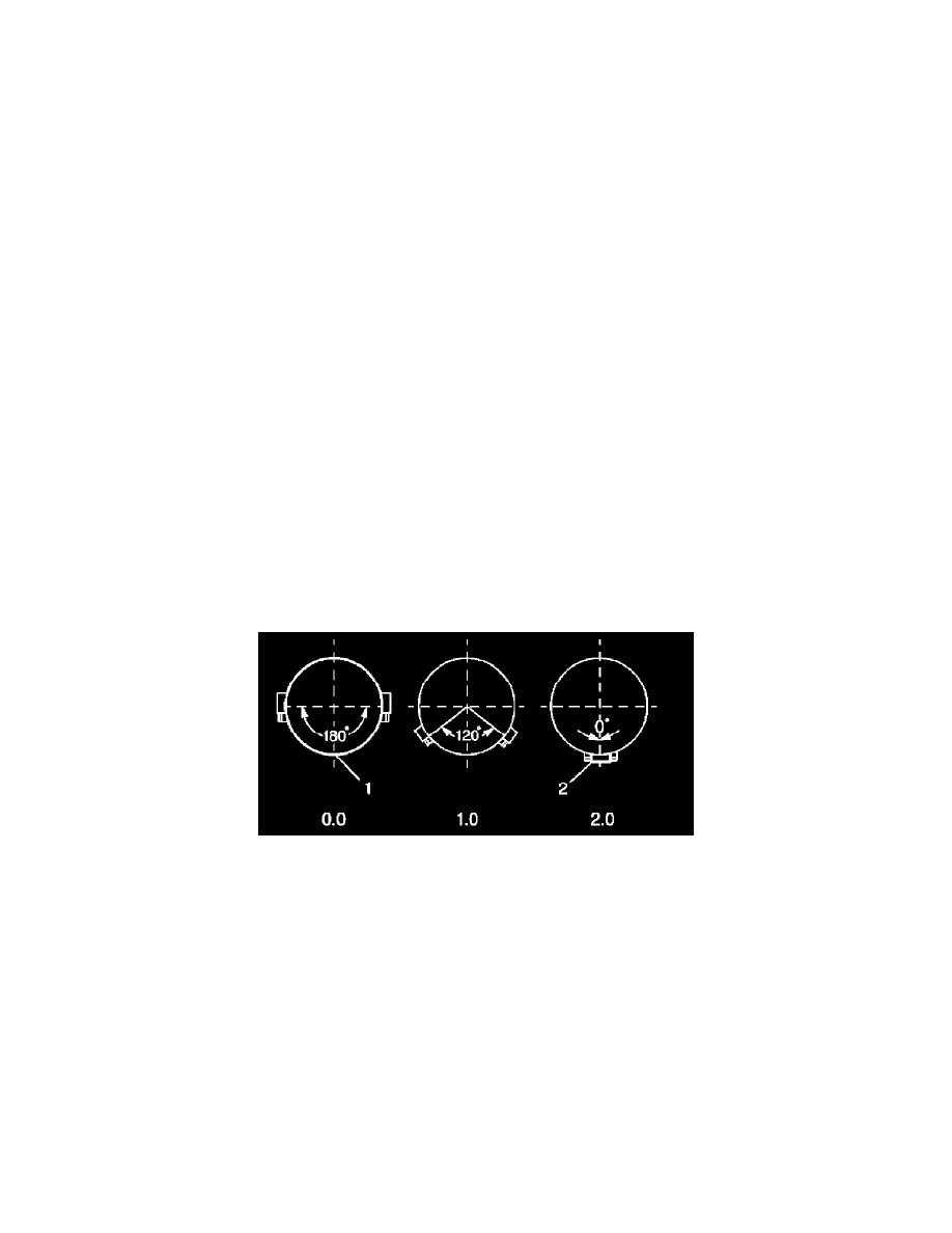
c. If the clamp heads over the original light spot, are now 90 to 180 degrees - at or above the 9 o'clock or the 3 o'clock positions - from the
original position at the bottom of the propeller shaft - 6 o'clock position - less total weight is required. Proceed to step 23.4.
d. Move the position of the clamp heads an equal distance on either side of the light spot between 1 and 120 degrees apart from each other to
reduce the total amount of weight in relation to the light spot.
e. Using the J 38792-25, or equivalent, recheck the positioning of the propeller shaft marks.
f.
If necessary, continue to move the position of the clamp heads an equal distance on either side of the light spot to a maximum of 120 degrees
apart from each other, until the greatest improvement to balance is achieved.
g. If improvement has been made to the balance of the propeller shaft, but the balance is still not satisfactory, still more total weight may be
required. Perform the following steps:
i.
Add a third clamp to the propeller shaft, next to the first and second clamps and with the clamp head directly on the light spot.
ii.
Move the position of the first and second clamp heads an equal distance on either side of the light spot between 1 and 120 degrees
apart from each other to arrive at a total amount of weight greater than two weights, but less than three weights in relation to the light
spot.
iii.
Using the J 38792-25, or equivalent, recheck the positioning of the propeller shaft marks.
iv.
If necessary, continue to move the position of the first and second clamp heads an equal distance on either side of the light spot to a