vauxhall Workshop Repair Guides

Vauxhall Workshop Service and Repair Manuals

ABS Control Unit, Remove and Install > < Electrical equipment, instruments Speedometer

Hydraulic Modulator with ABS Control Unit, Remove and Install

  Remove

LHD vehicles and diesel engine: Remove crash box – see operation "Crash Box, Remove and Install" in group "L".

Remove battery.

Detach multiplug (1) and multiplug (2) from relay carrier bracket.

Object Number: 2397663  Size: DEFAULT

Open relay carrier (1) cover.

For vehicle with diesel engines: Unclip relay (2) and fuse carrier (4) with wiring harness from relay carrier and place to one side – note cable routing.

Detach relay carrier (3) from relay carrier bracket and place to one side.

Unclip wiring harnesses from relay carrier bracket.

Object Number: 2397650  Size: DEFAULT

Remove relay carrier bracket (1) – 3 fastening nuts.

Detach retention clips (4) from brake lines.

For LHD vehicles: Detach brake lines from brake master cylinder. Detach brake lines (2) and (3) from hydraulic modulator – collect escaping fluid and close off openings.

For RHD vehicles: Detach brake lines (2) and (3) from hydraulic modulator collect escaping brake fluid and close off openings.

Object Number: 2397596  Size: DEFAULT

Unlock wiring harness plug (2) for ABS control unit (1) in direction of arrow and disconnect from ABS control unit.

Withdraw hydraulic modulator from bracket with ABS control unit and carefully remove – do not damage brake lines and attaching parts.

Caution

Place hydraulic modulator (3) to one side so that no brake fluid leaks out. Ensure the hydraulic modulator does not tilt.

  Remove

Transfer ABS control unit when removing hydraulic modulator – see operation "ABS Control Unit, Remove and Install".

Note:   Hydraulic modulators supplied by "Aftersales" are pre-filled. Only remove closure plugs after installation in bracket.

Object Number: 2397597  Size: DEFAULT

  Inspect

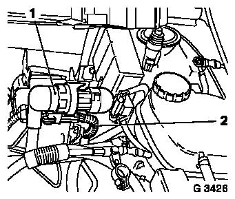
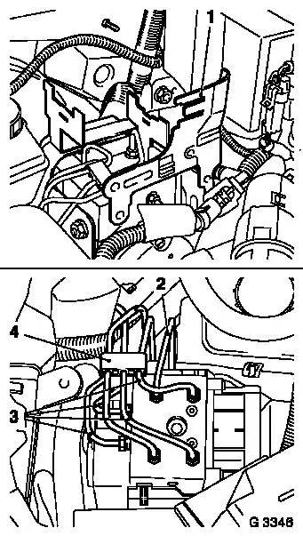
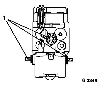
Check rubber mount (1) for hydraulic modulator, replace if necessary (Illus. G 3348 shows the hydraulic modulator as seen from below).

  Install

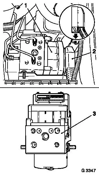
Carefully install hydraulic modulator in ABS bracket, ensure seating of hydraulic modulator on guide bolts is correct – do not damage brake lines and attaching parts.

Attach wiring harness plug to ABS control unit and lock.

For LHD vehicles: Attach brake lines to brake master cylinder and hydraulic modulator – tightening torque 16 Nm / 12 lbf. ft.

For RHD vehicles: Attach brake lines to hydraulic modulator – tightening torque 16 Nm / 12 lbf. ft.

Attach retention clip to brake lines.

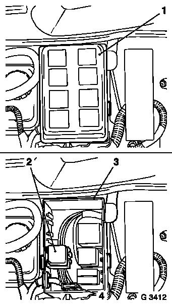
Install relay carrier bracket with new fastening bolts – tightening torque 20 Nm / 15 lbf. ft. Clip wiring harnesses onto relay carrier bracket. Connect relay carrier to relay carrier bracket.

Object Number: 2397598  Size: DEFAULT

For vehicles with diesel engine: Insert relay and fuse carrier in relay carrier with wiring harness and clip in position – ensure cable routing is correct.

Close relay carrier cover.

Attach multiplugs (2 off) to relay carrier bracket.

Install battery.

For LHD vehicles and diesel engine: Install crash box – see operation "Crash Box, Remove and Install" in group "L".

Bleed brake system – see operation "Brake System, Bleed and Check for Leaks". Top up brake fluid reservoir to "MAX". Screw lid on brake fluid reservoir.


Related Literature Units
-
-
-
-
-

ABS Control Unit, Remove and Install > < Electrical equipment, instruments Speedometer