|
PVC corrosion protection measures - PVC underseal
/ PVC protection from chippings
The areas that are susceptible to damage from chippings are
specially coated with PVC underseal. The aim of this is to achieve
permanent protection.
PVC underseal is applied on top of the priming.
Summary of the symbols in the illustrations with
the corresponding application thicknesses
|
Symbol
|
Description
|
Thickness of coat
|
Part Number
|
Catalogue Number
|
Unit
|
|
A
|
No coating
|
|
|
|
|
|
B
|
Runout area
|
0.5 - 0.0 mm
|
|
|
|
|
C
|
Underbody protection
|
0.5 mm
|
09 163 309
|
15 00 371
|
1 L
|
|
D
|
Cavity protection wax
|
0.3 mm
|
09 169 462
|
15 06 801
|
1 L
|
|
E
|
Aggregate protective wax
|
0.3 mm
|
|
|
|
|
F
|
Seam seal
|
|
90 093 639
|
15 04 520
|
310 ml
|
|
G
|
Protection from chippings
|
0.5 mm
|
09 121 538
|
15 00 367
|
500 ml
|
|
H
|
Closed film of wax
|
0.3 mm
|
09 121 548
|
15 00 369
|
300 ml
|
Summary of the following section diagrams
- Section A-A at the wheel housing
- Section B-B at the front floor
- Separation of views of front and rear of body
- Section C-C at rear of body
- Section D-D at rear frame
|
|
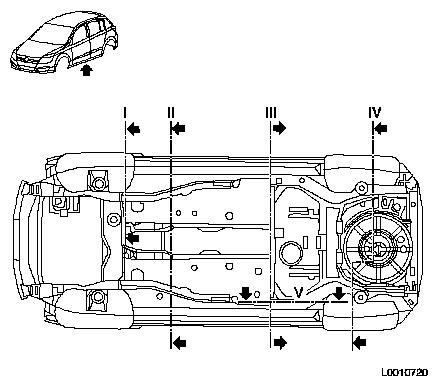
Floor group, front of body- below
| 1. |
Hatched areas with coat of PVC corrosion
protection, thickness 0.5 mm |
| 2. |
Areas which must not have a PVC corrosion
protection coating |
|
|
Floor group, rear of body - below
| 1. |
Hatched areas with coat of PVC corrosion
protection, thickness 0.5 mm |
| 2. |
Areas which must not have a PVC corrosion
protection coating |
|
|
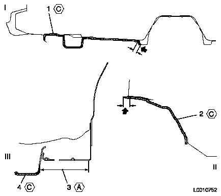
Section diagrams
See summary of section diagrams - illustration L0011485
|
I.
|
Section B-B
|
| |
1.
|
PVC corrosion protection, thickness 0.5 mm
|
|
II.
|
Section A-A
|
| |
2.
|
PVC corrosion protection, thickness 0.5 mm
|
|
III.
|
Section C-C
|
| |
3.
|
No coating
|
| |
4.
|
PVC corrosion protection, thickness 0.5 mm
|
Runout area: thickness 0.5 - 0 mm (arrows)
|
|
| 1. |
Section D-D |
| 2. |
PVC corrosion protection, thickness 0.5 mm |
| 3. |
No coating |
| 4. |
No coating |
Runout area: thickness 0.5 - 0 mm (arrows)
|
|
Rear wheel arch - left
The diagram of the left wheel arch should also be used for the
right wheel arch.
- Section E-E
| 1. |
Hatched areas with coat of PVC corrosion
protection, thickness 0.5 mm |
| 2. |
Areas which must not have a PVC corrosion
protection coating |
| 3. |
PVC corrosion protection, thickness 0.5 mm |
| 4. |
No coating |
| 5. |
No coating |
Runout area: thickness 0.5 - 0 mm (arrow)
|
|
Cross-sectional view, sill area - left
The diagram of the left sill area should also be used for the
right sill area.
- Section F-F
| 1. |
Hatched areas with coat of PVC corrosion
protection, thickness 0.3 mm |
| 2. |
Hatched areas with coat of PVC corrosion
protection, thickness 0.5 mm |
| 3. |
Area with coat of PVC corrosion protection,
thickness 0.3 mm |
| 4. |
Area with coat of PVC corrosion protection,
thickness 0.5 mm |
| 5. |
Section F-F |
Runout area: thickness 0.5 - 0 mm (arrows)
|
|
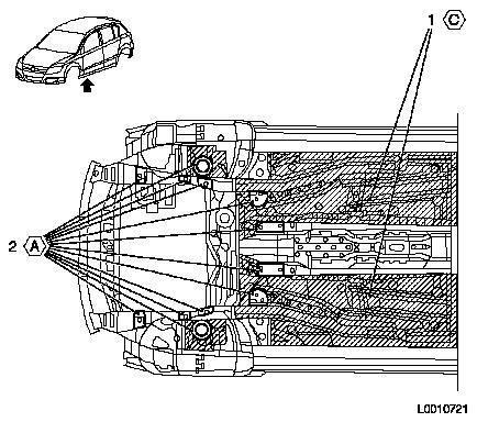
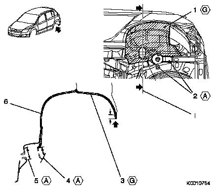
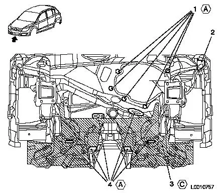
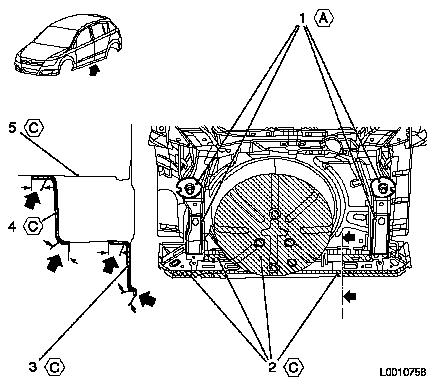
Bulkhead / underbody - front
| 1. |
Areas which must not have a PVC corrosion
protection coating |
| 2. |
View of bulkhead from front |
| 3. |
Hatched areas with coat of PVC corrosion
protection, thickness 0.5 mm |
|
|
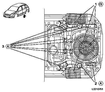
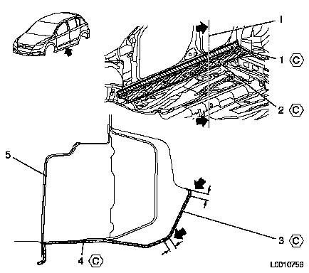
Replacement wheel well / underbody - rear
- Section F-F
| 1. |
Areas which must not have a PVC corrosion
protection coating |
| 2. |
Hatched areas with coat of PVC corrosion
protection, thickness 0.5 mm |
| 3. |
Area with coat of PVC corrosion protection,
thickness 0.5 mm |
| 4. |
Area with coat of PVC corrosion protection,
thickness 0.5 mm |
| 5. |
Section F-F |
Runout area: thickness 0.5 - 0 mm (arrows)
|
|
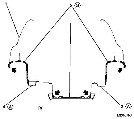
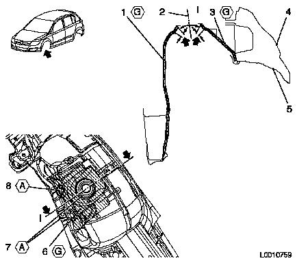
Front wheel arch - left
- Section G-G
| 1. |
Area with coat of PVC corrosion protection,
thickness 0.5 mm |
| 2. |
Section G-G |
| 3. |
Area with coat of PVC corrosion protection,
thickness 0.5 mm |
| 4. |
Wing |
| 5. |
Protective panelling for wheel housing |
| 6. |
Hatched areas with coat of PVC corrosion
protection, thickness 0.5 mm |
| 7. |
Areas which must not have a PVC corrosion
protection coating |
Runout area: thickness 0.5 - 0 mm (arrows)
|
|
Body sealing plug and cover
Sealing plug
Some of the sealing plugs used to close up openings in the body
are secured with a hot-melt adhesive.
The adhesive has already been applied to the new part.
A sealing plug with hot-melt adhesive is removed by supplying
heat with a hot air blower
Heat up the body area around the plug evenly until the adhesive
melts and the sealing plug can be removed.
Use a new component for installation
When installing make sure that the area where the hot-melt
adhesive must adhere is free from impurities and residues of
adhesive.
Before inserting a plug, heat the surrounding area of the body
uniformly (to approx. 120°C). Then insert the sealing plug and
push it on. The hot-melt adhesive runs and seals the area.
Afterwards, briefly heat the inserted sealing plug with the hot air
blower (mad.0.5 min).
|
