|
Balancer Shaft Unit, Remove and Install
 Remove Remove
| 1. |
Remove lower engine splash guard
|
| 2. |
Disconnect catalytic converter control oxygen sensor wiring
harness plug
|
| 3. |
Remove front exhaust pipe
|
| 4. |
Remove oil drain bolt
Note: Collect engine
oil
|
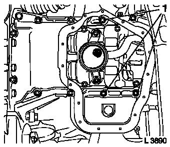
| 5. |
Disconnect wiring harness plug (1) for dynamic oil level
control and remove retaining ring (2)
|
| 6. |
Detach lower part of oil pan (3) from upper part of oil pan
|
|
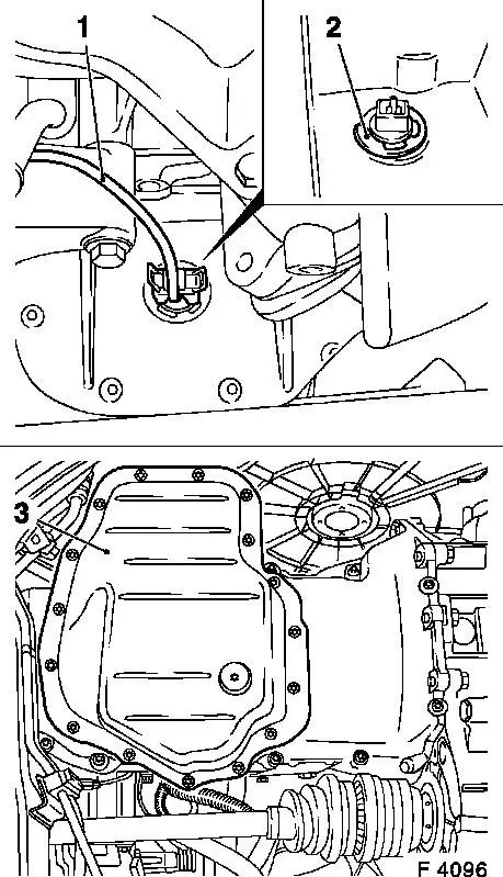
|
| 7. |
Clean sealing surfaces and remove gasket remnants.
|
| 8. |
Remove oil filter from oil pump with KM-726-A
|
| 9. |
Detach union nut (4) from turbocharger oil feed line
(turbocharger)
Note: Place collecting
basin underneath.
|
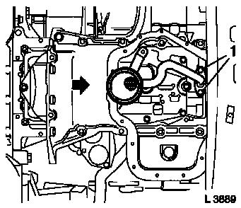
| 10. |
Detach bracket (3) from cylinder block
|
| 11. |
Detach union nut (1) from cylinder block flange and remove
turbocharger oil feed line (cylinder block) (2)
|
|
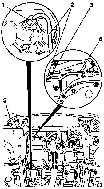
|
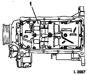
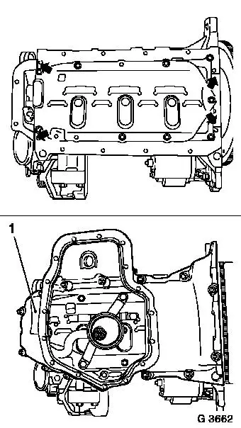
| 12. |
Detach oil pan top bolts (1) from transmission housing
|
| 13. |
Detach upper part of oil pan (2) from cylinder block and remove
oil pump
|
|
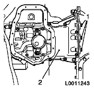
|
| 14. |
Detach 2x oil intake pipe bolts (1) from balancer shaft
unit
|
|
|
| 15. |
Move upper part of oil pan in direction of arrow and detach 2x
oil intake pipe bolts (1) from oil pump
|
| 16. |
Remove upper part of oil pan with oil intake pipe
|
|
|
| 17. |
Clean sealing surfaces and remove gasket remnants.
|
| 18. |
Remove oil baffle plate from balancer shaft unit
|
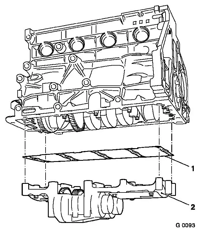
| 19. |
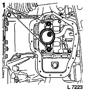
Detach balancer shaft unit (1) from cylinder block and
crankshaft bearing cap
| • |
Remove with balancer piece
|
|
|
|
 Install
| 20. |
Turn the crankshaft in the direction of engine rotation to the
mark "1st Cylinder TDC" using the fastening bolt for the toothed
belt drive gear.
|
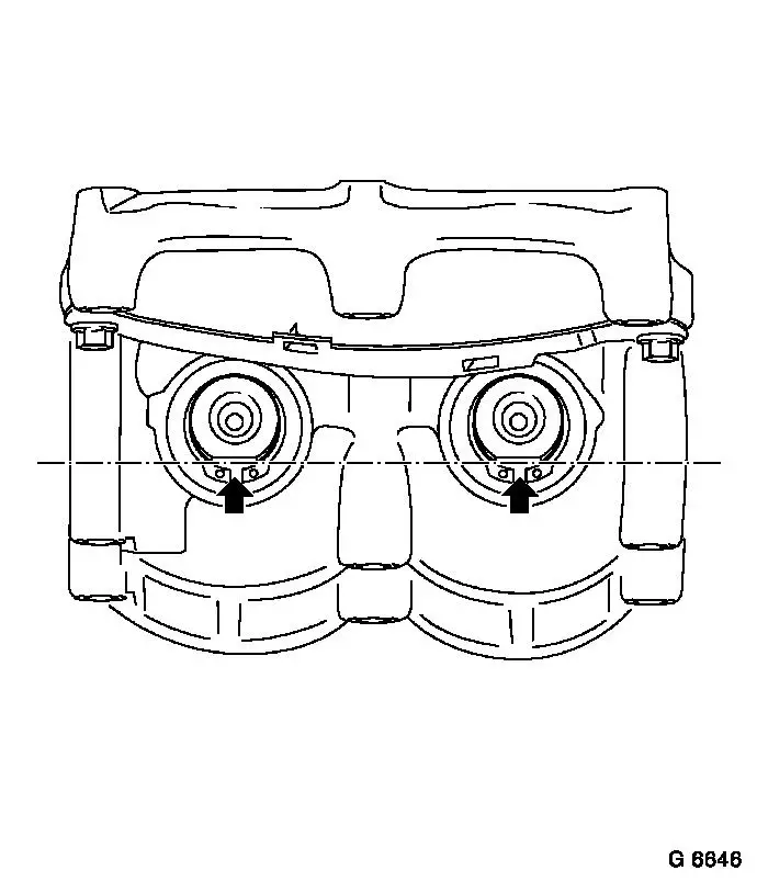
| 21. |
Turn balancer shafts so that both flattened sides (arrows)
point downward and form a horizontal line.
Note: If operations
have been performed on the crank drive that could affect the tooth
backlash between the balancer shafts and the crankshaft (e.g.
replacing the crankshaft, crankshaft bearing cap or balancer shaft
unit), the tooth backlash between balancer shafts and crankshaft
must be adjusted – see operation "Checking and adjusting
balancer shaft unit/crankshaft tooth backlash".
|
|
|
| 22. |
If no operations have been performed on crank drive that could
affect the tooth backlash between balancer shaft unit (2) and
crankshaft (e.g. removal and installation of con-rod bearing or
piston with con-rod), the same balancer piece (1) can be re-used
when installing.
|
|
|
| 23. |
Attach balancer shaft unit (2) with balancer piece (1) to
cylinder head and crankshaft bearing cap
| • |
Tighten all bolts uniformly 20 Nm +
45°
|
|
| 24. |
Attach oil baffle plate to balancer shaft unit 8 Nm
|
|
|
| 25. |
Apply a bead of adhesive sealing compound (black) to joints
(arrows) of oil pump and rear crankshaft bearing cap
|
| 26. |
Insert upper part of oil pan (1) with new gasket and oil intake
pipe
|
| 27. |
Attach oil intake pipe to oil pump with new seal ring 8 Nm
1)
|
| 28. |
Attach oil intake pipe to balancer shaft unit 10 Nm
|
|
|
| 29. |
Attach upper part of oil pan to cylinder block, oil pump and
transmission housing with new gasket
|
| 30. |
Insert contact surfaces of bolts (1) coated with surface
sealant (green)
Installation sequence:
| 1. |
Tighten all bolts loosely. |
| 2. |
Tighten bolts at cylinder block and oil pump 20 Nm |
| 3. |
Tighten bolts at transmission housing 40 Nm . |
|
|
|
| 31. |
Insert turbocharger oil feed line (cylinder block) and attach
to cylinder block flange with union nut 20
Nm
|
| 32. |
Attach turbocharger oil feed line union nut (cylinder block) to
turbocharger oil feed line (turbocharger) 20 Nm
|
| 33. |
Attach turbocharger oil feed line bracket to cylinder block
35 Nm
|
| 34. |
Coat oil filter seal ring with a thin layer of engine oil and
attach to oil pump 15 Nm
|
| 35. |
Insert dynamic oil level control plug-in connection into upper
section of oil pan with new seal ring and fix in position with
retaining ring
|
| 36. |
Attach lower section of oil pan to upper section of oil pan
with new gasket and new bolts 8 Nm +
30°
|
| 37. |
Attach oil drain bolt to lower section of oil pan with new
gasket 10 Nm
|
| 38. |
Connect wiring harness plug for dynamic oil level control
|
| 39. |
Install front exhaust pipe with new gasket 35 Nm
|
| 40. |
Connect wiring harness plug for catalytic converter control
oxygen sensor
|
| 41. |
Route wiring harness
Note: Note routing of
wires
|
| 42. |
Install lower engine splash guard
|
| 43. |
Top up engine oil quantity to "MAX" mark on oil dipstick
|
1 ) Recut thread before use and insert bolts with
bolt locking compound (red). Installation time including torque
check should not exceed 10 minutes.
|
