|
Check and adjust balancer shaft unit/crankshaft
tooth backlash
 Remove Remove
| 1. |
Remove lower engine splash guard
|
| 2. |
Disconnect catalytic converter control oxygen sensor wiring
harness plug
|
| 3. |
Remove front exhaust pipe
|
| 4. |
Remove oil drain bolt
Note: Collect engine
oil
|
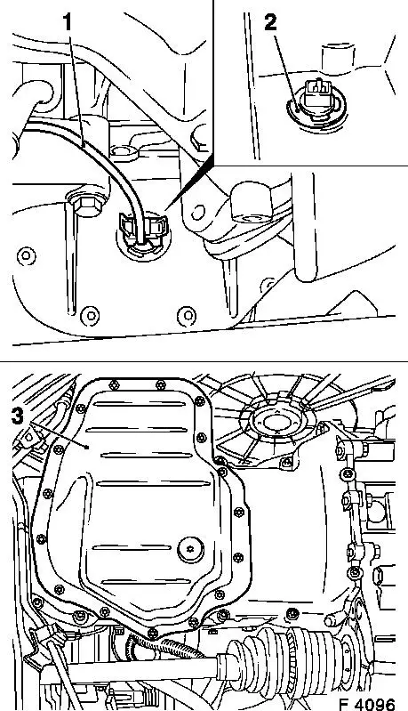
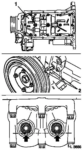
| 5. |
Disconnect wiring harness plug (1) for dynamic oil level
control and remove retaining ring (2)
|
| 6. |
Detach lower part of oil pan (3) from upper part of oil pan
|
|
|
| 7. |
Clean sealing surfaces and remove gasket remnants.
|
| 8. |
Remove oil filter from oil pump with KM-726-A
|
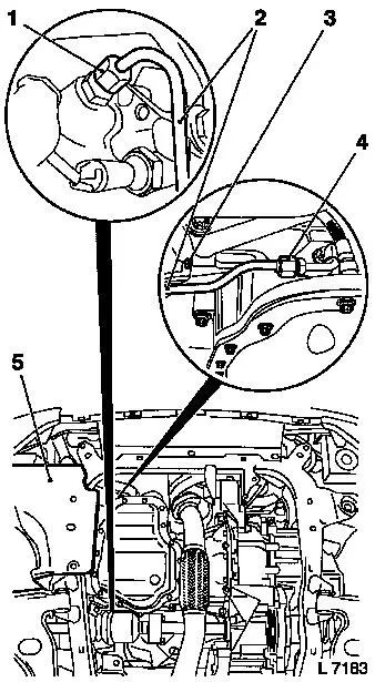
| 9. |
Detach union nut (4) from turbocharger oil feed line
(turbocharger)
Note: Place collecting
basin underneath.
|
| 10. |
Detach bracket (3) from cylinder block
|
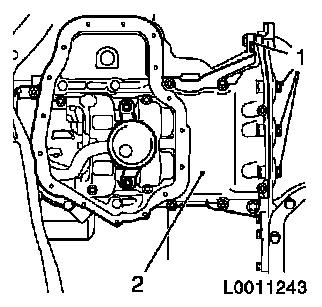
| 11. |
Detach union nut (1) from cylinder block flange and remove
turbocharger oil feed line (cylinder block) (2)
|
|
|
| 12. |
Detach oil pan top bolts (1) from transmission housing
|
| 13. |
Detach upper part of oil pan (2) from cylinder block and remove
oil pump
|
|
|
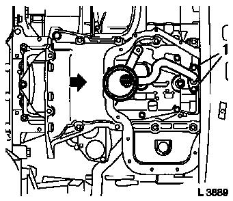
| 14. |
Detach 2x oil intake pipe bolts (1) from balancer shaft
unit
|
|

|
| 15. |
Move upper part of oil pan in direction of arrow and detach 2x
oil intake pipe bolts (1) from oil pump
|
| 16. |
Remove upper part of oil pan with oil intake pipe
|
|
|
| 17. |
Clean sealing surfaces and remove gasket remnants.
|
| 18. |
Remove oil baffle plate (1) from balancer shaft unit.
|
| 19. |
At toothed belt drive gear fastening bolt, turn crankshaft in
direction of engine rotation to "Cylinder no.1 TDC " (mark 2).
|
| 20. |
In this crankshaft position, the flattened sides (arrows) of
both balancer shafts must point down and form a horizontal
line.
|
|
|
 Install
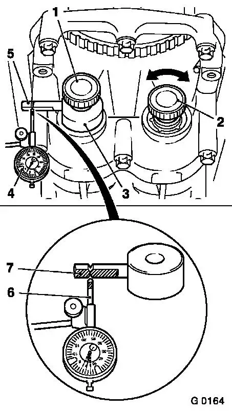
| 21. |
Screw measuring device KM-949 (3)
into 1st balancer shaft (intake side) using long knurled bolt (1)
and hand-tighten
Note: Measuring arm (5)
must point in "9 o'clock" direction
|
| 22. |
Screw short knurled bolt (2) into 2nd balancer shaft (exhaust
side) and also hand-tighten
|
| 23. |
Fit dial gauge bracket with dial gauge KM-798 (4) to cylinder block and place dial gauge
plunger (6) against measuring arm of measuring device KM-949 under pre-tension
Note: The plunger must
be placed exactly between the notch marks, vertically to the flat
plane (7)
|
| 24. |
Determine left and right stop positions by turning knurled bolt
(2) backwards and forwards. Set dial of dial gauge to zero.
|
|
|
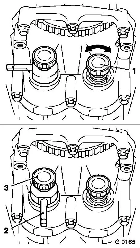
| 25. |
Move 2nd balancer shaft (exhaust side) forwards and backwards
again at knurled bolt (1) - read off tooth backlash from dial gauge
at same time.
|
| 26. |
Permissible backlash is: 0.02 mm to 0.06 mm.
|
| 27. |
The tooth backlash must be measured in 4 different positions -
to do this, continue rotating crankshaft at toothed belt drive gear
fastening bolt in steps of 90° in direction of engine rotation
until measuring arm (2) is in the "6 o'clock" position.
|
| 28. |
Then loosen the knurled bolt (3), move measuring arm to "9
o'clock" again and repeat measurement.
|
| 29. |
If any of the 4 measurements is out of tolerance (0.02 mm to
0.06 mm) the tooth backlash must be adjusted.
|
|
|
|
