|
Repair engine using a short block
 Remove Remove
| 2. |
- Remove manual transmission from engine

- Remove MTA-manual transmission from engine
|
| 3. |
Drain engine oil
| • |
Place collecting pan underneath.
|
| • |
Detach oil filter housing cover
|
| • |
Take out oil filter element
|
|
| 4. |
Detach thrust plate and clutch disk
|
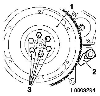
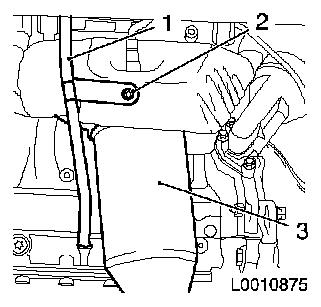
| 5. |
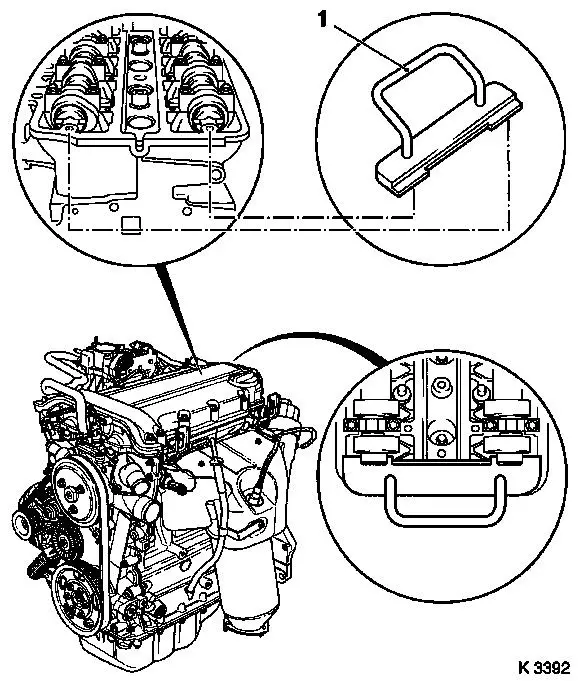
Remove flywheel (1)
Note: KM-6263 remains attached to the engine. To provide a
clearer illustration, KM-6263 is not
shown here
|
|
|
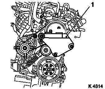
| 6. |
7. Detach right hand engine bracket (1)
|
|
|
| 7. |
8. Tighten oil drain bolt 10 Nm
|
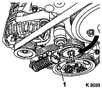
| 8. |
Remove ribbed V-belt
| • |
Mark direction of rotation
|
| • |
Apply tension to ribbed V-belt tensioner (arrow) clockwise with
KM-6131
|
| • |
Relieve tension on ribbed V-belt tensioner
|
|
|
|
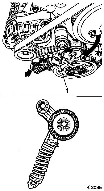
| 9. |
Remove ribbed V-belt tensioner
| • |
Apply tension to ribbed V-belt tensioner in the direction of
the arrow with KM-6131
|
| • |
Release ribbed V-belt tensioner
|
| • |
Unscrew 2x bolts (arrows)
|
| • |
Take out ribbed V-belt tensioner
|
|
|
|
| 10. |
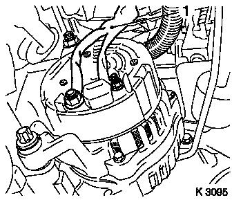
Detach engine wiring harness
| • |
Unscrew alternator wiring harness (1)
|
| • |
Unscrew starter wiring harness
|
|
|
|
| 11. |
Detach alternator
| • |
Remove 2x screwed connections
|
|
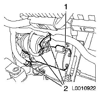
| 12. |
Disconnect cable connections (2) from starter (1)
|
|
|
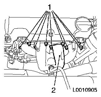
| 15. |
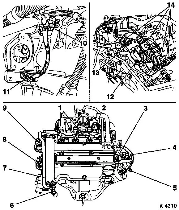
Detach engine management wiring harness
| • |
Remove cover - injectors
|
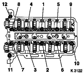
| • |
Disconnect 11x wiring harness plugs
| – |
Oil pressure switch (6), coolant temperature sensor (8),
camshaft sensor (9), throttle valve module (2), engine control unit
(12), exhaust gas recirculation valve (4), ignition module (3),
oxygen sensor, mixture control (5), knock sensor (10), crankshaft
sensor (11), injectors (1)
|
|
| • |
Detach earth cable, engine control unit (13)
|
| • |
Unclip wiring trough (7)
|
| • |
Unclip 4x wiring harness from brackets (14)
|
|
|
|
| 16. |
Remove coolant hose from exhaust gas recirculation valve
|
| 17. |
Remove dipstick guide tube
|
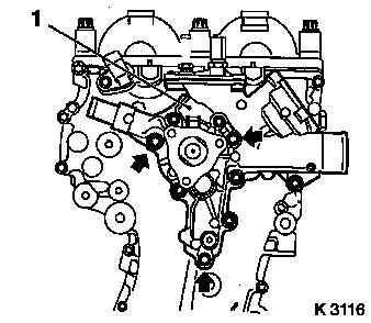
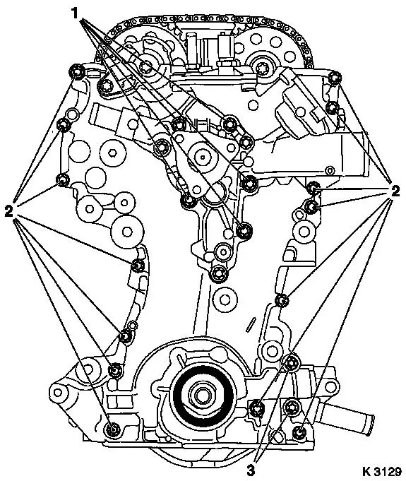
| 18. |
Detach coolant pump (1)
Note: Note guide
sleeves when removing
| • |
Place collecting pan underneath.
|
| • |
Unscrew 9x bolts
Note: Note differing
bolt lengths (arrows = short bolts)
|
|
|
|
| 20. |
Remove oil dipstick guide tube (1)
| • |
Detach from exhaust manifold (3)
|
| • |
Remove from cylinder block
|
|
|
|
| 21. |
Detach exhaust manifold (2)
|
|
|
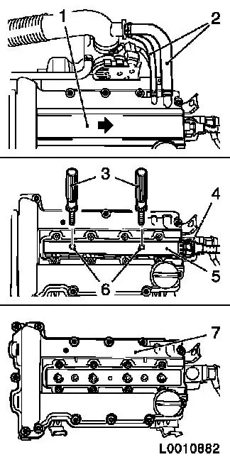
| 22. |
Remove engine vent hoses (2) from cylinder head cover
|
| 23. |
Remove ignition module
| • |
Disconnect cooling module wiring harness plug (4)
|
| • |
Pull the cover of the ignition module (1) away from the
cylinder head cover in the direction of the arrow
|
Important: Do not tilt
|
| • |
Remove ignition module (5) from spark plugs with KM-6009 (3)
|
|
| 24. |
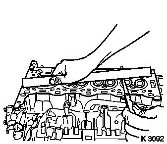
Detach cylinder head cover (7) from cylinder head
|
|
|
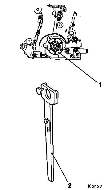
| 25. |
Slacken bolt, crankshaft hub (1)
Note: 2.people
|
|
|
| 26. |
Adjust the camshafts
| • |
Turn crankshaft evenly in direction of engine rotation with
KM-956-1/-2 until KM-953 (1) engages in
the camshaft groove as far as the stop
|
|
| 27. |
Detach crankshaft hub
Note: Observe correct
fitting position
|
|
|
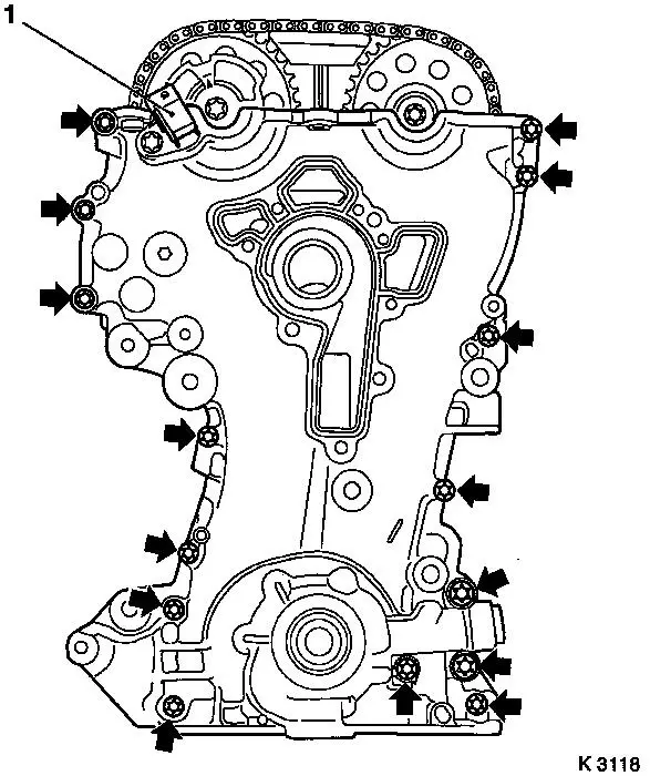
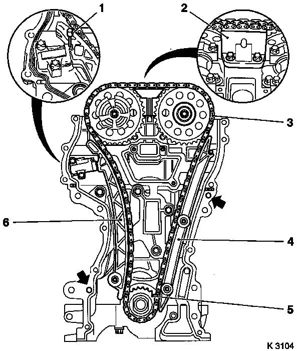
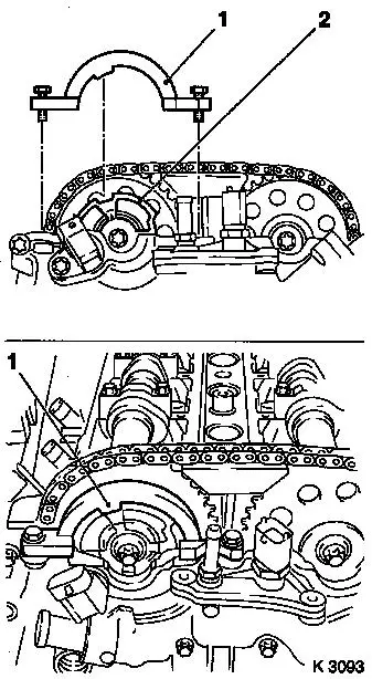
| 29. |
Remove timing case
Note: Do not damage
camshaft sensor (1)
| • |
Unscrew 15x bolts (arrows)
Note: Note bolt
lengths
|
|
|
|
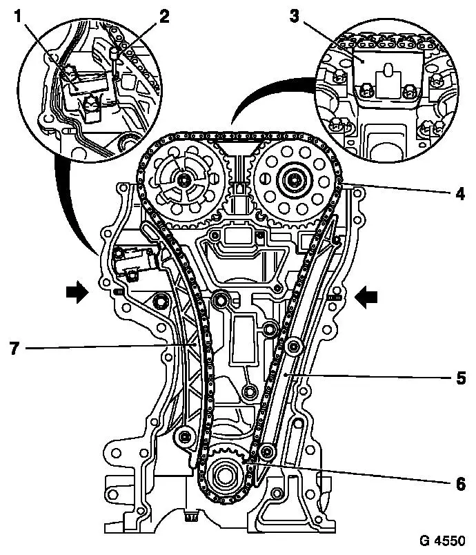
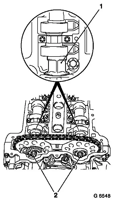
| 30. |
Detach chain drive
| • |
Slacken 2x bolts, camshaft sprocket
| – |
Counterhold the camshafts on the hexagon
|
|
| • |
Lock chain tensioner (1)
|
| • |
Detach sliding rail (3), guide rail (5), tension rail (7),
camshaft sprockets
|
| • |
Take out timing chain (4) with drive gear (6)
|
| • |
Take out timing case gasket
|
|
|
|
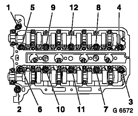
| 31. |
Remove cylinder head
| • |
Unscrew 12x cylinder head bolt
Note: Comply with
sequence illustrated
| – |
Slacken 12x bolts (90°)
|
| – |
Slacken 12x bolts 180°)
|
|
| • |
Place cylinder head on wooden blocks
|
| • |
Remove cylinder head gasket
|
|
|
|
| 32. |
Detach oil filter housing
|
| 34. |
If present: detach oil baffle plate
|
| 35. |
Remove crankshaft sensor
|
| 36. |
Detach cylinder block from KM-412
| • |
Attach cylinder block to workshop crane.
|
| • |
Detach 8x bolted connections
|
| • |
Detach from cylinder block KM-412-18
|
|
 Install
| 37. |
Attach cylinder block to KM-412
| • |
Attach KM-412-18 to cylinder
block
|
|
| 39. |
Tap 6x guide sleeves into cylinder block
|
| 40. |
Clean sealing surfaces.
| • |
Cylinder block, cylinder head, cylinder head cover, oil filter
housing, crankshaft bearing bridge, timing case, oil pan, coolant
pump. exhaust manifold
|
|
| 41. |
Visually check components
| • |
Cylinder block, cylinder head, cylinder head cover, oil filter
housing, crankshaft bearing bridge, chain drive, timing case, oil
pan, coolant pump, exhaust manifold
|
|
| 42. |
If the cylinder head is to be checked and overhauled: Detach
all external attaching parts from cylinder head
|
| 43. |
Check flatness of cylinder head
| • |
With straight edge and feeler gauge
|
|
|
|
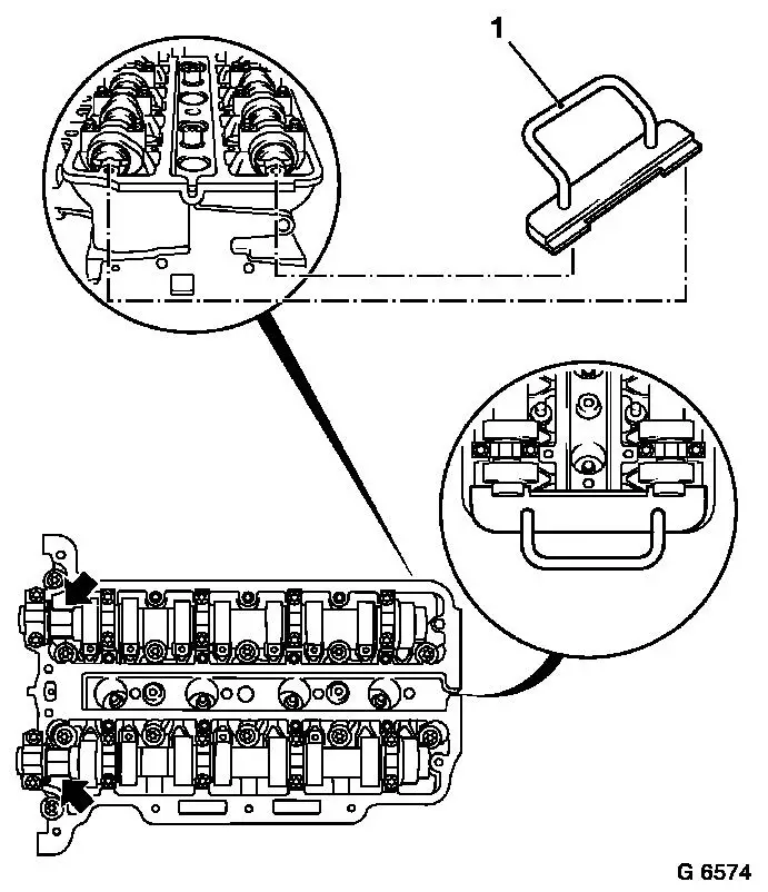
| 44. |
Lock crankshaft
| • |
Unscrew closure bolt (1)
|
| • |
Insert KM-952 (2)
| – |
Turn crankshaft evenly until KM-952
engages
|
|
|
|
|
| 45. |
If present: attach oil baffle plate
|
| 46. |
Attach oil filter housing
| • |
Oil Filter Element, Replace
|
| • |
Attach oil filter housing cover
|
|
| 47. |
Adjust the camshafts
| • |
Insert KM-953 (1)
| – |
Turn the camshafts by the hexagon (arrows)
|
|
|
|
|
| 48. |
Install cylinder head
| • |
Replace gasket
Note: Marking TOP/OBEN
must point upwards
|
| • |
Replace cylinder head bolts
|
| • |
Tighten 12x cylinder head bolt 25 Nm +
60° + 60° + 60 °
Note: Note correct
tightening sequence
|
|
|
|
| 49. |
Attach timing chain
| • |
Replace timing case gasket
Note: Note correct
seating (arrows)
|
| • |
Position exhaust camshaft sprocket
|
| • |
Place timing chain in position (3)
|
| • |
Insert intake camshaft sprocket in timing chain with phase
sensor disc
| – |
Screw in bolt
Note: It must be
possible to turn the phase sensor disc by hand
|
|
|
|
|
| 50. |
Attach timing chain tension rail (6)
Note: Ensure timing
chain is seated correctly
|
| 51. |
Attach timing chain guide rail (4)
Note: Ensure timing
chain is seated correctly
|
| 52. |
Attach timing chain sliding rail (2)
|
| 53. |
Relieve tension on chain tensioner
|
|
|
| 54. |
Attach coolant pump
| • |
Attach with short bolts (2)
Note: Ensure guide
sleeves are correctly seated (arrows)
|
|
|
|
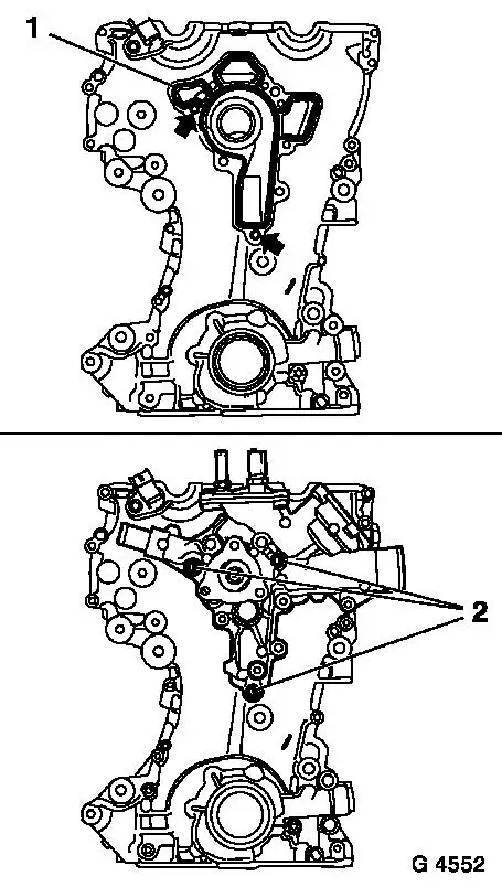
| 55. |
Attach timing case.
| • |
Screw in all bolts
Note: Note correct
tightening sequence
|
| • |
Tighten 5x bolt M6 (1) 8 Nm
|
| • |
Tighten 14x bolt M6 (2) 8 Nm
|
| • |
Tighten 2x bolt M10 (3) 35 Nm
|
|
|
|
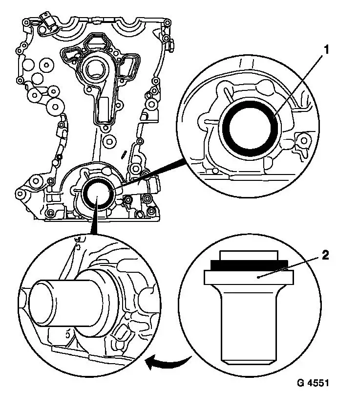
| 56. |
Replace front crankshaft seal ring (1)
| • |
Smear sealing lips with silicone grease
|
| • |
Drive in flush using KM-960
|
|
| 57. |
Remove KM-952 and KM-953
Note: Locking tools may
not be used for counterholding
|
|
|
| 58. |
Attach crankshaft hub (1)
Note: Marking must
point upwards
| • |
Counterhold with KM-956-1/-2 (2)
Note: Use a second
person
|
| • |
Tighten bolt 150 Nm + 45° +
15°
|
|
| 59. |
Attach crankshaft ribbed V-belt pulley
| • |
Tighten 6x bolt 8 Nm
| – |
Counterhold against bolt, crankshaft hub
|
|
|
|
|
| 61. |
Attach KM-954 (1)
| • |
Turn phase sensor disc (2) until KM-954 can be attached to timing case
|
|
|
|
| 62. |
Fasten camshaft sprockets
Note: First of all
tighten bolt of intake camshaft sprocket
| • |
Tighten 2x bolt (2) 10 Nm
Note: Tightening torque
10 Nm serves to fix the camshaft sprockets and the phase sensor
disc
| – |
Counterhold the camshafts on the hexagon (1)
|
|
|
| 63. |
Take out locking tools KM-952 , KM-953 , KM-954
|
| 64. |
Tighten camshaft sprockets
Note: First of all
tighten bolt of intake camshaft sprocket
| • |
Tighten 2x bolt 50 Nm + 60°
|
|
|
|
| 66. |
Take out locking tools KM-952 , KM-953 , KM-954
|
| 68. |
Tighten closure bolt crankshaft bearing bridge 50 Nm
|
| 70. |
Attach crankshaft sensor
|
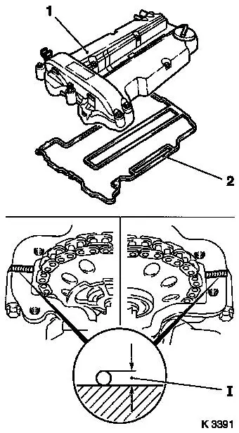
| 71. |
Attach cylinder head cover (1)
| • |
Replace gasket and seal rings (2)
|
| • |
Apply sealant (dimension I = 2 mm)
| – |
Complete assembly work within 10 minutes
|
|
| • |
Attach 2x engine vent hose
|
|
|
|
| 72. |
Connect ignition module to spark plugs and attach to cylinder
head
|
| 73. |
Attach ignition module cover to cylinder head cover
|
| 74. |
Insert exhaust manifold gasket
|
| 75. |
Install exhaust manifold
| • |
Tighten 9x nut 15 Nm (2
passes)
|
|
| 77. |
Install dipstick guide tube
|
| 79. |
Attach engine transport shackle
|
| 80. |
Attach coolant hoses to coolant pump and exhaust gas
recirculation valve
|
| 81. |
Attach engine management wiring harness
| • |
Connect 14x wiring harness plugs
|
| • |
Attach earth cable, engine control unit
|
| • |
Attach cover - injectors
|
|
| 82. |
Attach starter to cylinder block
|
| 83. |
Attach starter wiring harness
|
| 84. |
Install alternator
| • |
Insert alternator into bracket
|
| • |
Tighten 2x screwed joint 35 Nm
|
| • |
Attach alternator wiring harness
|
|
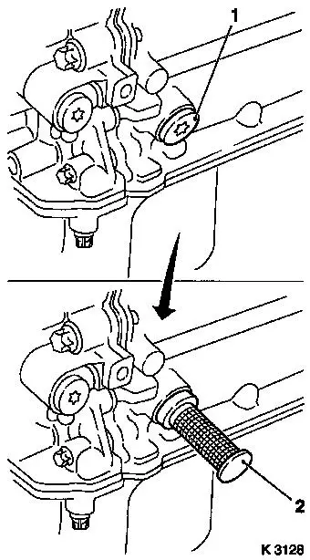
| 85. |
Attach ribbed V-belt tensioner -
| • |
Apply tension to ribbed V-belt tensioner in the direction of
the arrow with KM-6131 (2)
|
|
|
|
| 86. |
Attach ribbed V-belt pulley, coolant pump
|
| 87. |
Insert ribbed V-belt
| • |
Position ribbed V-belt
| – |
Ensure correct running direction and installation position
|
|
| • |
Apply tension to ribbed V-belt tensioner with KM-6131
|
| • |
Relieve tension on ribbed V-belt tensioner
|
|
| 88. |
Attach right hand engine bracket
|
| 89. |
Fit flywheel
Note: Use new bolts
| • |
Clean 6x thread in crankshaft
|
| • |
Tighten 6x bolt 35 Nm + 60° +
15°
| – |
Apply screw locking compound
|
|
|
| 90. |
Attach thrust plate and clutch disk
|
| 91. |
Top up engine oil.
| • |
Observe specified engine oil quantity
|
|
| 92. |
- Attach manual transmission to engine
- Attach MTA manual transmission to engine
|
|
