|
Timing Case, Remove and Install
 Remove Remove
| 2. |
Disconnect battery
| • |
Detach earth connection from negative terminal
|
|
|
| 3. |
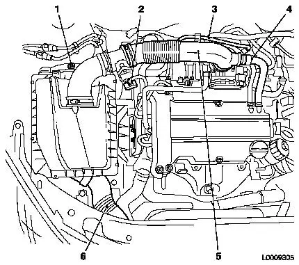
Remove air cleaner housing
| • |
Disconnect mass air flow sensor wiring harness plug (2)
|
| • |
Unclip tank vent line (3)
|
| • |
Detach engine vent hose (4) from air intake hose
|
| • |
Detach air intake hose (5) from throttle valve body
|
| • |
Detach air cleaner housing
| – |
Unclip rubber mounting at the bottom
|
| – |
Remove air intake pipe (6)
|
|
|
|
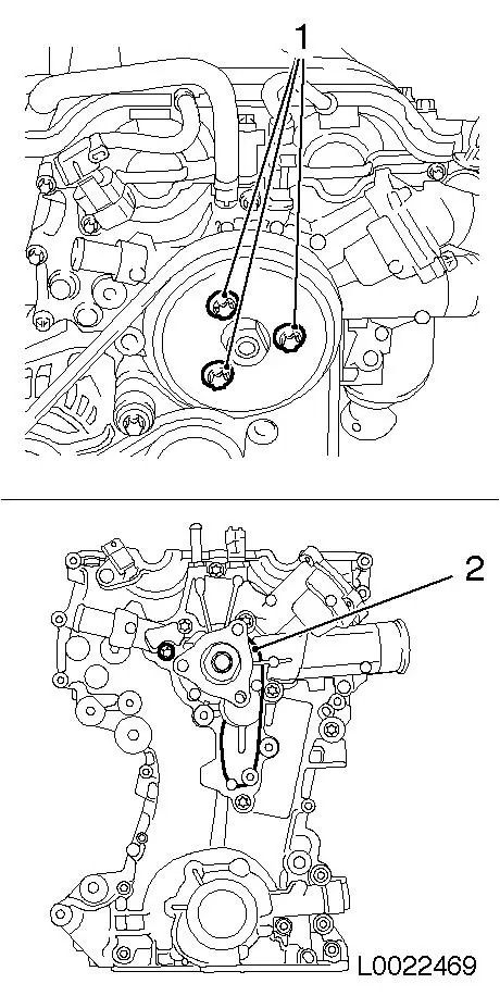
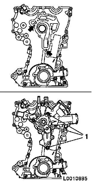
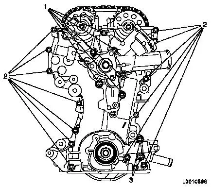
| 4. |
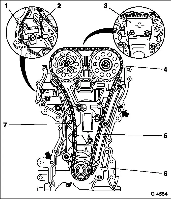
Raise vehicle by its full height
|
| 5. |
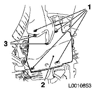
Remove right engine splash guard (2)
| • |
Remove 2x body-bound rivets (3)
|
|
|
|
| 6. |
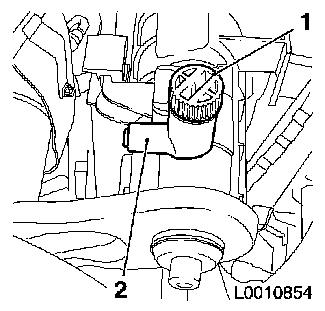
Drain coolant
| • |
Place collecting pan underneath.
|
| • |
Attach suitable hose to drain connection (2)
|
| • |
Open coolant drain screw (1)
|
| • |
Close coolant drain screw
|
|
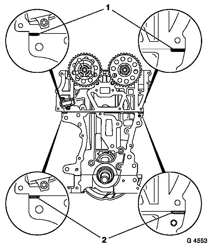
|
|
| 8. |
Remove compressor
Note: For vehicles with
air conditioning
|
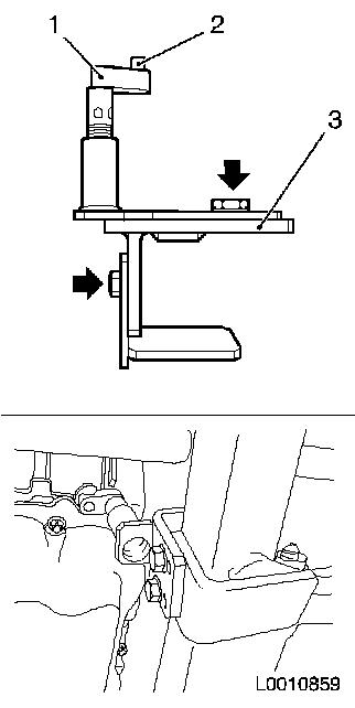
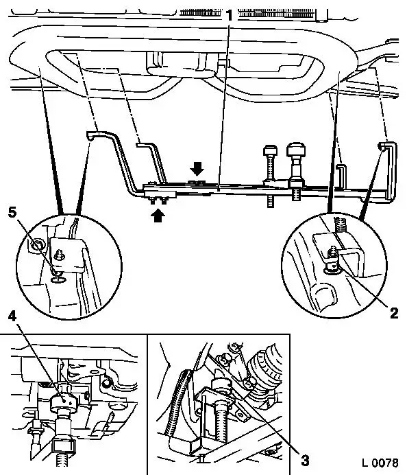
| 9. |
Insert KM-6173 (3)
| • |
Slacken 4x bolts (arrows) and hand-tighten
|
| • |
Align KM-6173 at front axle body
|
| • |
Wind up the support bearing (1)
| – |
Journal (2) must sit in mount at cylinder block
|
|
|
|
|
|
| 10. |
Attach KM-6001-A (1)
Note: Attaching KM-6001-A guarantees perfect alignment of the
drive unit with the front axle body
| • |
Slacken 3x bolts (arrows) in adjusting rails
|
| • |
Insert KM-6001-A
| – |
The journals (2) and (5) must sit in the guide holes of the
front axle body
|
|
| • |
Tighten 3x bolts in adjusting rails
|
| • |
Adjust support bearings, front (4) and rear (3)
| – |
Raise support bearings up to the stop on the guide journals
Note: The guide
journals must be seated free from play in the support bearings
|
|
|
|
| 11. |
Lower vehicle by its full height
|
| 12. |
Remove engine damping block, right hand side
| • |
Unscrew 6x bolts (1) and (2)
|
| • |
Remove engine damping block with bracket
|
|
|
|
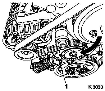
| 13. |
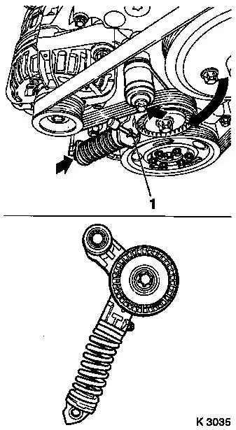
Remove ribbed V-belt
| • |
Mark direction of rotation
|
| • |
Apply tension to ribbed V-belt tensioner (arrow) clockwise with
KM-6131
|
| • |
Relieve tension on ribbed V-belt tensioner
|
|
|
|
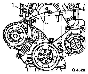
| 14. |
Detach engine damping block support (1) from timing case and
cylinder block
|
|
|
| 15. |
Remove ribbed V-belt tensioner
| • |
Apply tension to ribbed V-belt tensioner in the direction of
the arrow with KM-6131
|
| • |
Release ribbed V-belt tensioner
|
| • |
Unscrew 2x bolts (arrows)
|
| • |
Take out ribbed V-belt tensioner
|
|
|
|
|
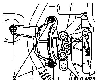
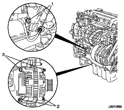
| 16. |
Detach alternator
| • |
Detach alternator wiring harness
|
| • |
Detach 2x screwed connections (2) and (3)
|
|
|
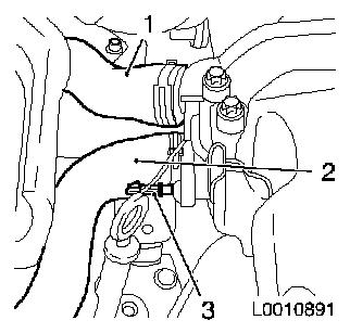
| 17. |
Remove coolant hose (1) from thermostat housing
|
| 18. |
Remove thermostat housing
|
| 19. |
Remove coolant hose (2) from coolant pump
|
| 20. |
Disconnect oil pressure switch (3) wiring harness plug
|
|
|
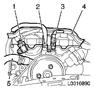
| 21. |
Disconnect wiring harness plug for camshaft sensor (1) and
coolant temperature sensor (3)
|
| 22. |
Detach coolant hose (2)
|
| 23. |
Unclip wiring trough (4)
|
|
|
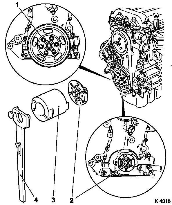
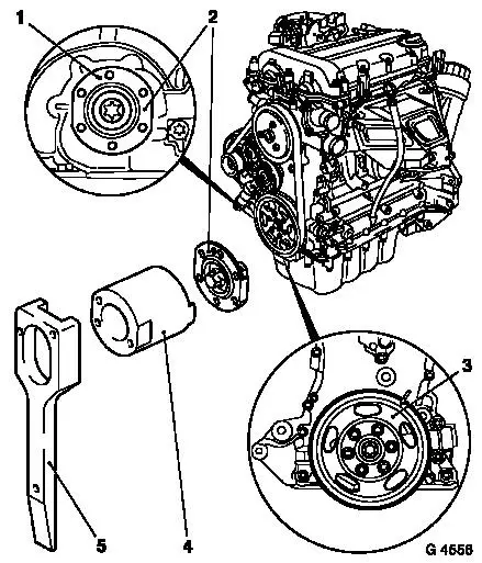
| 24. |
Remove belt pulley (1) from coolant pump
|
| 25. |
Remove coolant pump (2) from timing case
Note: Be careful of the
guide sleeves when taking out the coolant pump
| • |
Unscrew 8x bolts
Note: Note different
bolt lengths
|
|
|
|
| 26. |
Remove engine vent hose (2) from cylinder head cover
|
| 27. |
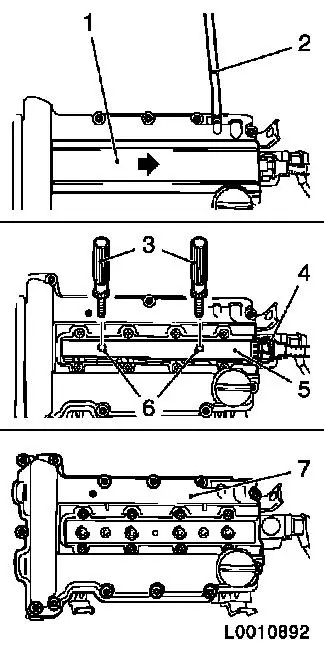
Remove ignition module
| • |
Disconnect ignition module wiring harness plug (4)
|
| • |
Pull the cover of the ignition module (1) away from the
cylinder head cover in the direction of the arrow
|
| • |
Remove ignition module (5) from spark plugs with KM-6009 (3)
Note: Do not tilt
|
|
| 28. |
Detach cylinder head cover (7) from cylinder head
|
|
|
|
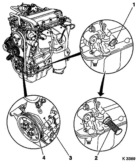
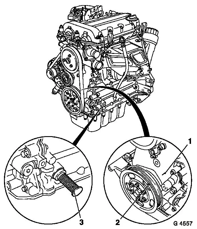
| 29. |
Remove closure bolt crankshaft bearing bridge (1)
|
| 30. |
Adjust TDC of combustion stroke of cylinder 1
Note: Marking on the
crankshaft belt pulley (4) must align with the cast projection (3)
on the timing case
| • |
Insert KM-952 (2)
| – |
Turn crankshaft evenly until KM-952
engages
|
|
|
|
|
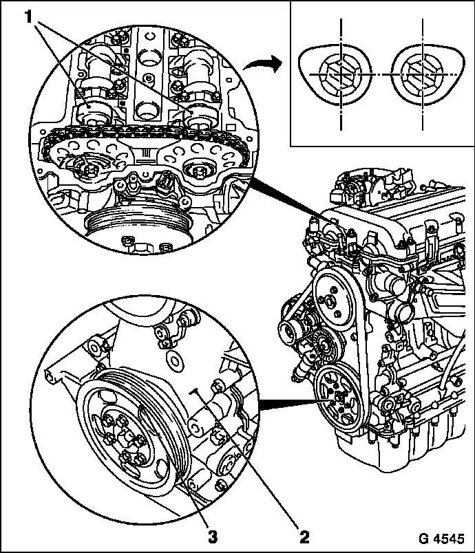
| 31. |
Check position of camshafts
| • |
Insert KM-953 (1)
| – |
KM-953 must engage in groove of
camshafts
|
|
|
|
|
| 32. |
Detach crankshaft ribbed V-belt pulley (1)
| • |
Unscrew 6x bolts
| – |
Counterhold against bolt, crankshaft hub
|
|
|
| 33. |
Slacken bolt, crankshaft hub
Note: Use a second
person
|
| 34. |
Detach crankshaft hub (2)
| • |
Take out crankshaft hub
|
|
|
|
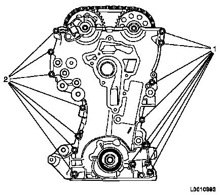
| 35. |
Remove timing case
| • |
Unscrew 15x bolts (1) and (2)
|
|
|
|
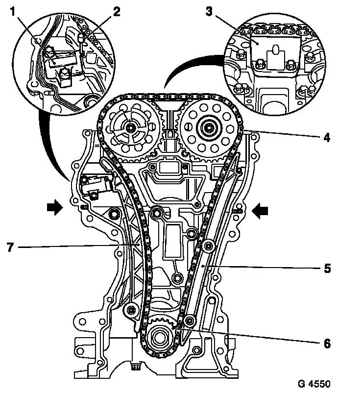
| 36. |
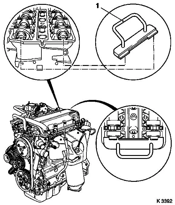
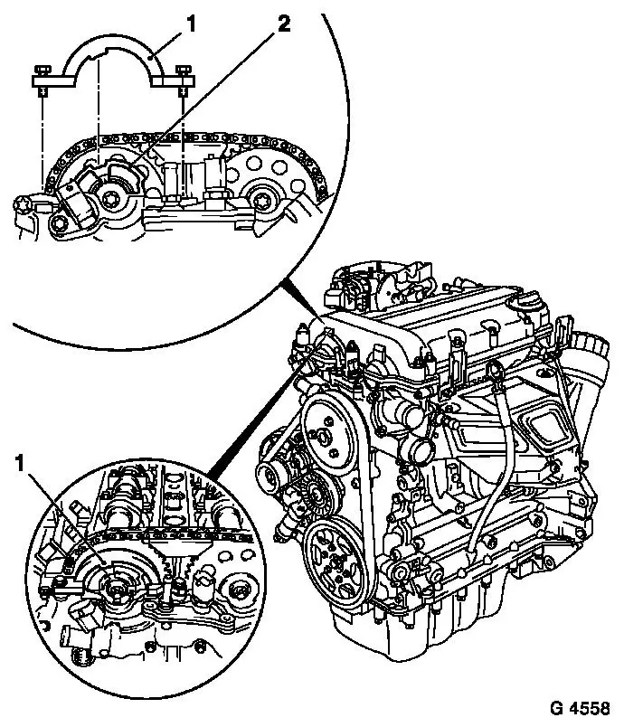
Detach chain drive
| • |
Lock chain tensioner (1)
| – |
Press back and insert KM-955-1
(2)
|
|
| • |
Remove sliding rail (3)
|
| • |
Take out timing chain (4) and drive gear (6)
|
|
| 37. |
Take out timing case gasket
|
| 38. |
Clean sealing surfaces and remove gasket remnants.
Note: if a two-part
timing case gasket has been used, the sealing compound must be
removed in the area of the cylinder head gasket
|
|
| 39. |
Prise seal ring out of timing case with suitable tool
Note: Do not damage
sealing surfaces
|
 Install
|
| 40. |
Clean sealing surfaces and remove gasket remnants.
|
| 41. |
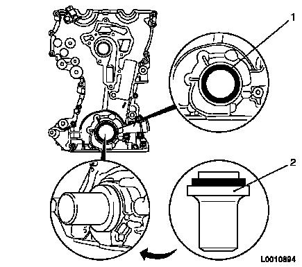
Coat sealing lip of new seal ring with silicone grease
|
| 42. |
Push seal ring on to KM-960 (2)
|
| 43. |
Drive seal ring into timing case until flush using KM-960
|
|
| 44. |
Insert new coolant pump gasket into timing case
|
| 45. |
Ensure guide sleeves are correctly seated (arrows)
|
| 46. |
Attach coolant pump to timing case with short bolts (1)
|
|
|
|
Important: The timing case must
be fitted within 10 minutes of applying the silicone sealing
compound
|
| 47. |
Apply sealant
| • |
Any elastomer projections present from the cylinder head gasket
(1) must be cut off flush and replaced by a bead of silicone
sealing compound (2) approx. 2 mm thick
Note: If no projecting
elastomer is present, the bead of silicone sealant (2) can be
applied direct
|
|
|
|
| 48. |
Timing Case Gasket, Replace
| • |
Place new timing case gasket in position
| – |
Ensure guide sleeves are correctly seated (arrows)
|
|
|
| 49. |
Place drive gear (6) on crankshaft
|
Important: Ensure that the
tension side (exhaust side) of the timing chain is under
tension
|
| 50. |
Place timing chain (4) over drive gear and camshaft
sprockets
|
| 51. |
Attach tension rail (7) to cylinder block
|
| 52. |
Attach guide rail (5) to cylinder block
|
| 53. |
Attach sliding rail (3) to cylinder head
|
| 54. |
Take KM-955-1 (2) out of chain
tensioner (1)
|
|
|
| 55. |
Attach timing case.
Note: Comply with
assembly sequence
| • |
Attach coolant pump to cylinder head and cylinder block
| – |
Tighten 5x bolts (1) 8 Nm
|
|
| • |
Attach timing case to cylinder head, cylinder block and to base
plate of cylinder block
| – |
Tighten 13x bolt M6 (2) 8 Nm
|
| – |
Tighten 2x bolt M10 (3) 35 Nm
|
|
|
|
| 56. |
Remove KM-952 and KM-953
Note: Special tools may
not be used for counterholding
|
|
| 57. |
Note installation position of crankshaft hub (2) -.
| • |
Marking (1) must point upwards
|
|
| 58. |
Attach crankshaft hub to crankshaft with new bolt
| • |
Counterhold with KM-956 (5)
|
| • |
Tighten bolt 150 Nm + 45° +
15°
|
|
| 59. |
Attach crankshaft belt pulley (3) to crankshaft hub
| • |
Counterhold against the bolt of the crankshaft hub
|
|
|
|
| 60. |
Set crankshaft to just before cylinder 1 TDC of combustion
stroke
Note: Turn crankshaft
slowly and smoothly
| • |
Turn the bolt of the crankshaft hub approx. 720°
|
| • |
The marking (3) on the crankshaft belt pulley is just before
the cast projection (2) on the timing case
|
| • |
In this position, the cams of cylinder 1 are just before "TDC
of combustion stroke" (both cams point outwards)
|
|
|
|
| 61. |
Insert KM-952 (3) in aperture and
simultaneously
| • |
Continue turning the crankshaft slowly in the direction of
engine rotation by the bolt of the crankshaft hub until the
crankshaft locking pin engages as far as the stop in the base plate
of the cylinder block or crank web
|
| • |
In this position, the marking (2) on the crankshaft belt pulley
must align with the projection (1) on the timing case
|
|
|
|
| 62. |
Insert KM-953 (1) into camshaft
Note: If KM-953 cannot be inserted, perform basic setting -
see operation "Timing, Adjust"
| • |
KM-953 must engage as far as the stop
in the grooves of the camshafts
|
|
|
|
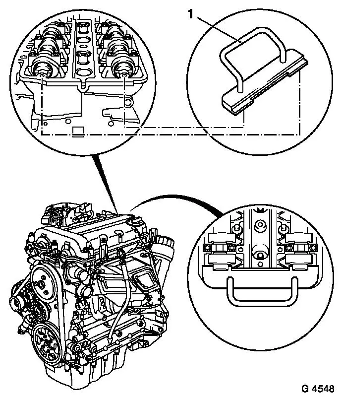
| 63. |
Place KM-954 (1) on the phase sensor
disc (2) and attach to timing case
Note: If KM-954 cannot be inserted, perform basic setting -
see operation "Timing, Adjust"
|
|
| 64. |
Take out or remove KM-954 , KM-953 and KM-952
|
| 65. |
Install closure bolt with new seal ring into cylinder block
base plate 60 Nm
|
| 66. |
Clean sealing surfaces and remove gasket remnants.
|
|
| 67. |
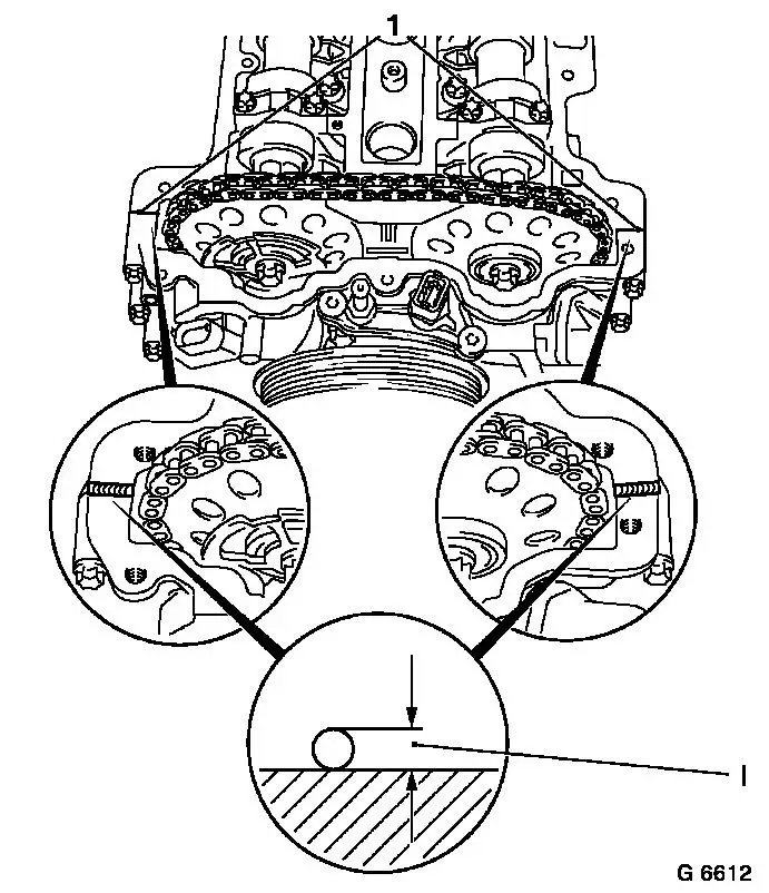
Apply sealant
Note: The cylinder head
cover must be fitted within 10 minutes of applying the silicone
sealing compound
| • |
Disconnect projecting part of timing case gasket (1) flush with
cylinder head/timing case
|
| • |
Apply a bead of silicone sealing compound approx. 2 mm thick
(dimension I)
|
|
|
| 68. |
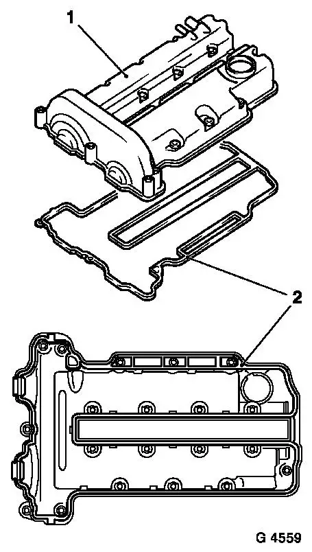
Install cylinder head cover
| • |
Insert new gasket (2) in cylinder head cover (1)
|
| • |
Connect ignition module to spark plugs and attach to cylinder
head
|
| • |
Attach ignition module cover to cylinder head cover
|
| • |
Connect ignition module wiring harness plug
|
| • |
Attach engine vent hose to cylinder head cover
|
|
|
|
| 69. |
Attach coolant hose to coolant pump
|
| 70. |
Connect wiring harness plugs, coolant temperature sensor,
camshaft sensor and oil pressure switch
|
| 71. |
Clip wiring trough to cylinder head cover
|
| 72. |
Attach coolant hoses to coolant pump
|
| 73. |
Attach thermostat housing
|
| 74. |
Install alternator
| • |
Insert alternator into bracket
|
| • |
Tighten 2x screwed joint 35 Nm
|
| • |
Attach alternator wiring harness
|
|
| 75. |
Attach ribbed V-belt tensioner -
| • |
Apply tension to ribbed V-belt tensioner in the direction of
the arrow with KM-6131 (2)
|
|
|
|
| 76. |
Insert ribbed V-belt
| • |
Position ribbed V-belt
| – |
Ensure correct running direction and installation position
|
|
| • |
Apply tension to ribbed V-belt tensioner with KM-6131
|
| • |
Relieve tension on ribbed V-belt tensioner
|
|
| 77. |
Fit engine damping block to body
| • |
Tighten 3x bolt (2) 35 Nm
|
|
| 78. |
Attach engine damping block bracket to engine damping block
support
| • |
Tighten 3x bolt (1) 55 Nm
|
|
|
|
| 79. |
Install air cleaner housing
| • |
Attach air cleaner housing to wheelhouse
|
| • |
Attach air intake hose to throttle valve module
|
| • |
Attach engine vent hose to timing case
|
| • |
Connect wiring harness plug, air mass flow meter
|
|
| 81. |
Remove KM-6001-A and KM-6173
|
| 82. |
Attach right engine splash guard
| • |
Install 2x body-bound rivets
|
|
| 83. |
Attach compressor
Note: For vehicles with
air conditioning
|
| 85. |
Attach earth connection to battery
|
| 86. |
Program volatile memories
|
| 87. |
Fill and bleed cooling system 
|
|
