|
Transmission, Remove and Install (Z18XER/A18XER -
AF17)
Note: In order to
ensure that the drive unit is correctly aligned when the bolts for
the left engine damping block are slackened, the drive unit must be
aligned with the front axle body using KM-6001-B . Instructions for attaching KM-6001-B are given in the following.
 Remove Remove
| 1. |
Remove battery and battery support 
|
| 2. |
Remove lower engine compartment cover
Note: If present.
|
| 3. |
Remove front exhaust pipe, catalytic converter and centre
silencer
|
|
| 4. |
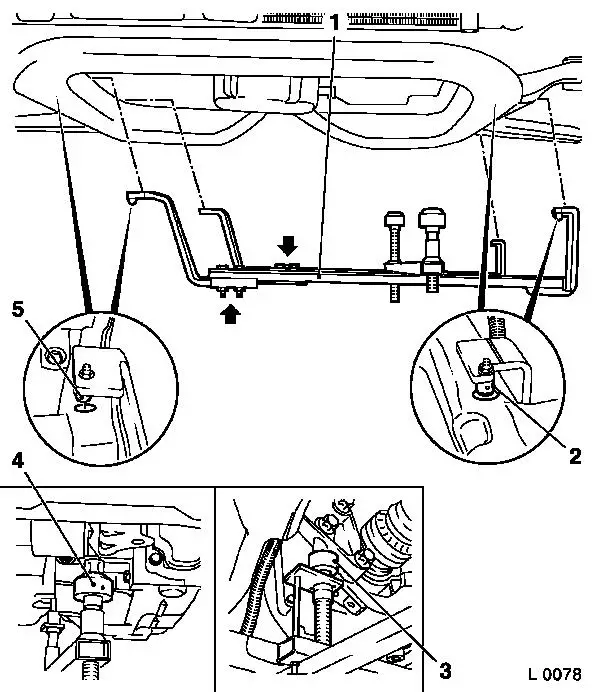
Attach KM-6001-B to front axle
body
| • |
Release 2x bolt (arrows) for adjustment rails on KM-6001-B (1)
|
| • |
Insert KM-6001-B as shown
Note: 2x journals (2)
and (5) must sit flush in the guide holes of the front axle
body.
|
| • |
Tighten 2x bolt for adjustment rails
|
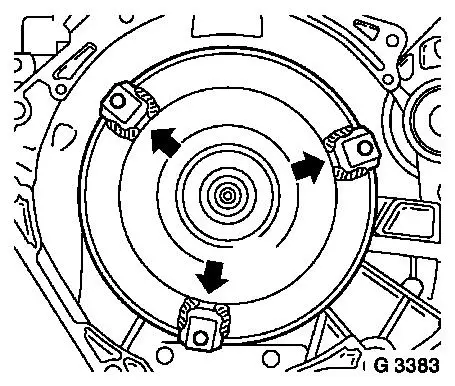
| • |
Twist up front support bearing (4)
| – |
as far as the stop on the guide pin of the front engine damping
block
Note: The guide pins
must sit in the support bearings with no play.
|
|
| • |
Twist up rear support bearing (3)
| – |
as far as the stop on the guide pin of the rear engine damping
block bracket
Note: The guide pins
must sit in the support bearings with no play.
|
|
|
|
|
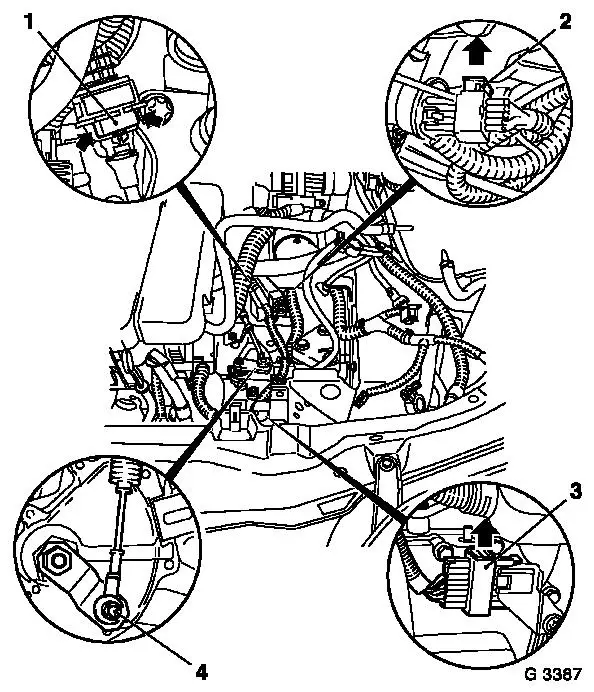
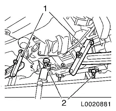
| 5. |
Release and disconnect wiring harness plug for selector lever
position switch (2)
| • |
Open lock in the direction of the arrow
|
|
| 6. |
Release and disconnect wiring harness plug (3) for transmission
wiring harness
| • |
Open lock in the direction of the arrow
|
|
| 7. |
Clip selector actuation cable from counterhold
| • |
Open retaining clamp (1)
|
| • |
Detach selector actuation cable (4) from actuation lever.
|
|
|
| 8. |
Detach selector actuation cable bracket
|
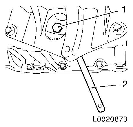
| 9. |
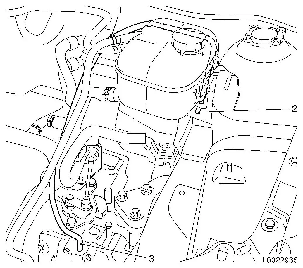
Remove fluid filler tube (2) with dipstick
|
|
|
| 10. |
Release transmission at top
|
|
|
| 11. |
Remove front axle body
Note: KM-6001-B remains on front axle body and may not be
moved.
|
| 12. |
Remove 2x axle shaft from transmission
Note: Place collecting
pan underneath - transmission fluid escapes. Axle shafts remain in
the wheel hubs. Attach axle shafts to underbody.
| • |
Seal 2x apertures in transmission with plugs
|
|
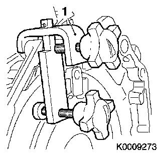
| 13. |
Detach converter from drive disc
| • |
Remove 2x sealing plugs
|
| • |
Lock drive disc with KM-911 (2)
|
| • |
Unscrew 3x bolt (1)
Note: Turn drive disc
by a further 120° each time.
|
|
|
|
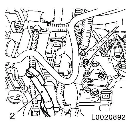
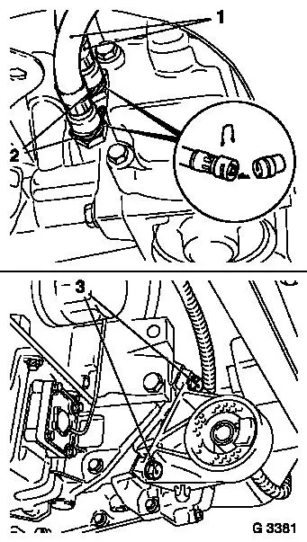
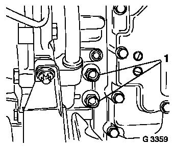
| 14. |
Detach 2x fluid cooler line (1) from transmission
Note: Place collecting
pan underneath - transmission fluid will escape
Note allocation of the fluid cooler lines.
| • |
Detach 2x retaining clamp (2)
|
| • |
Seal apertures in transmission with KM-924
|
|
| 15. |
Detach front engine damping block
|
|
|
| 16. |
Detach wiring harness bracket
|
| 17. |
Detach rear engine damping block
|
|
|
| 18. |
Detach transmission venting hose from transmission
|
| 19. |
Detach left engine damping block from engine damping block
bracket
|
|
|
Important: Do not damage wiring
harnesses and attaching parts
|
| 20. |
Lower engine and transmission with MKM-883-1 approx. 5 cm
|
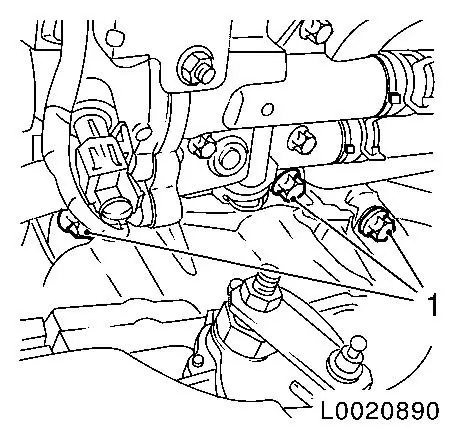
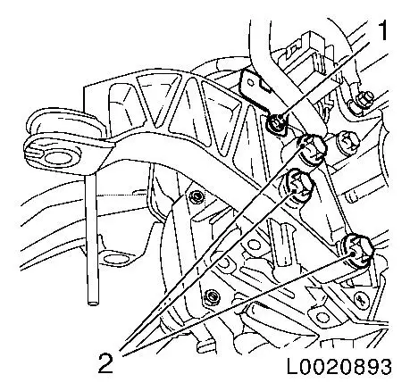
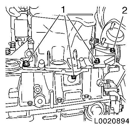
| 21. |
Detach transmission from oil pan
| • |
Unscrew 3x M10 bolts (1)
|
| • |
Unscrew M10 bolt connection (2)
|
|
|
|
|
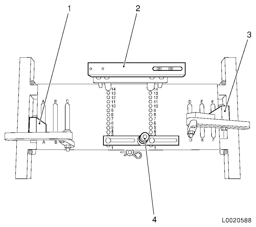
| 22. |
Place transmission holder DT-47648 on
KM-904 and preinstall as shown in the
illustration:
|
Component
|
Position on base plate
|
Designation
|
|
DT-47648-2
(4)
|
2
|
Converter housing support
|
|
DT-47648-3
(2)
|
14
|
Transmission housing support
|
|
DT-47648-5 left
(1)
|
A
|
Support with rear transmission swivel arm
|
|
DT-47648-5 right
(3)
|
F
|
Support with front transmission swivel arm
|
|
|
Important: It is essential to
follow the manufacturer's instructions for transmission holder
DT-47648 .
|
| 23. |
Attach transmission holder DT-47648
to transmission
Note: Before placing in
position slacken all bolt connections of the swivel arms and
supports as far as the base plate. Adjust the supports for the
converter housing and transmission housing using the spindles until
they are as low as possible.
| • |
Align transmission holder DT-47648
under transmission
|
| • |
Attach 2x swivel arms (1) to transmission
|
| • |
Tighten the bolt connections of the swivel arms, starting from
the transmission and going as far as the base plate
Note: Align the swivel
arms so that as little leverage as possible is created.
|
| • |
Position supports for converter housing and transmission
housing on transmission
| – |
Twist up the spindles (2)
|
|
| • |
Tighten bolt connections of the supports
|
|
|
|
|
Important: Ensure that the
converter remains in the transmission.
Do not damage wiring harnesses and attaching parts
|
| 24. |
Remove transmission
| • |
Unscrew 2x M12 bolts (1)
|
| • |
Press transmission off engine and slowly lower the hydraulic
jack
|
|
|
| 25. |
Secure torque converter so it does not fall out
|
|
|
Important: Do not damage the
attaching parts when putting the transmission down.
|
| 26. |
If required: detach transmission from transmission holder DT-47648
|
| 27. |
When replacing the transmission:
| • |
Drain the oil cooler as much as possible
|
| • |
Blow low-pressure compressed air through the oil cooler
|
| • |
Blow low-pressure compressed air in both directions through the
fluid cooler lines from the connections
|
| • |
Transfer attaching parts
|
|
 Install
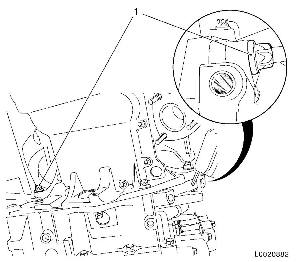
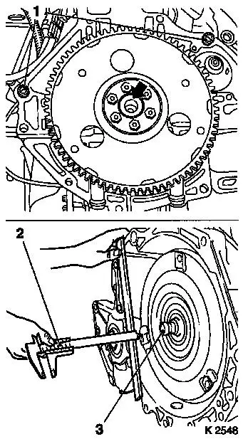
| 28. |
If required: attach transmission to transmission holder DT-47648
Note: It is important
that the manufacturer's instructions for DT-47648 are followed.
Before installing the transmission: thinly coat the centring seat
(arrow) for the converter in the crankshaft with grease. When
replacing the transmission, ensure that the two guide bushings (1)
sit in the engine flange.
|
| 29. |
Check converter centring journal (3) for fretting
|
| 30. |
Measure the distance between the converter connecting threads
and the mating surface of the transmission housing with a calliper
gauge (2)
|
|
|
| 31. |
Recut thread (arrows) in converter
|
|
|
|
| 33. |
Raise transmission with hydraulic jack and transmission holder
DT-47648 and align it
| • |
Place transmission so that it is in even contact with the
engine
Note: Ensure it is
seated perfectly.
Do not damage wiring harnesses and attaching parts
|
|
| 34. |
Fasten transmission to engine with 2x bolts
| • |
Tighten 2x M12 bolts (1) 60 Nm
|
|
| 35. |
Detach transmission holder DT-47648
from transmission
| • |
Lower hydraulic jack with transmission holder DT-47648 and extend
|
|
|
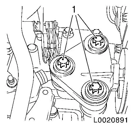
| 36. |
Fasten transmission at the bottom
| • |
Install transmission on fluid sump
| – |
Tighten 3x M10 bolts (1) 40 Nm
|
|
| • |
Tighten bolt connection (2) 40
Nm
|
|
|
|
| 37. |
Attach converter to drive disc
| • |
Lock drive disc with KM-911 (2)
|
| • |
Tighten 3x bolt (1)
Note: Insert bolts with
retaining compound
Turn drive disc by a further 120° each time.
| – |
Stage 1: tighten 3x bolts evenly to 20
Nm
|
| – |
Stage 2: Tighten 3x bolts to 45 Nm
+20° +25°
|
|
|
| 38. |
Attach 2x covers to transmission
|
|
|
| 39. |
Attach engine damping block to transmission at front
| • |
Tighten 2x bolt (1) 80 Nm
|
|
|

|
| 40. |
Attach rear engine damping block to transmission
| • |
Tighten 3x bolt (2) 80 Nm
|
|
| 41. |
Attach wiring harness bracket
|
|
|
| 42. |
Install axle shafts in transmission
|
| 43. |
Attach oil cooler lines to transmission
Note: Note
allocations.
| • |
Use 2x new O-ring (1)
Note: Fluid cooler
lines must be heard to engage.
|
|
|
|
| 44. |
Raise engine and transmission with MKM-883-1 and align
|
| 45. |
Attach left engine damping block to engine damping block
bracket
| • |
Screw in 3x bolt (1)
Note: Do not tighten
the 3 bolts yet.
|
|
Important: When installing the
front axle body, ensure that the support bearings with KM-6001-B sit properly in the guide pin of the front
engine damping block and the rear engine damping block bracket. If
necessary: correct installation position of engine and transmission
using MKM-883-1 .
|
| 46. |
Install front axle body
Note: Do not yet
install front exhaust pipe, catalytic converter, centre muffler,
battery support and battery.
|
| 47. |
Fasten left engine damping block
| • |
Tighten 3x bolt (1) 55 Nm
|
|
|
|
| 48. |
Fasten transmission at top
| • |
Tighten 3x bolt (1) 60 Nm
|
|
|
|
| 49. |
Attach selector actuation cable bracket
| • |
Tighten 2x bolt (1) 20 Nm
|
|
| 50. |
Install fluid filler tube (2) with dipstick
Note: Use new seal
ring
|
|
|
|
| 51. |
Connect transmission venting hose (3)
Note: Check that the
bleeder hose is correctly routed and clipped in (1). The free end
of the bleeder hose (2) must be laid at least 10 cm lower.
|
|
| 52. |
Attach selector actuation cable
| • |
Attach to selector actuation cable bracket
|
| • |
attach to actuation lever
|
|
| 53. |
Connect and lock wiring harness plug for transmission wiring
harness
|
| 54. |
Connect and lock selector lever position switch wiring harness
plug
|
| 55. |
Install battery support and battery
|
| 57. |
Install front exhaust pipe, catalytic converter and centre
silencer
|
| 58. |
Attach lower engine compartment cover
Note: If present.
|
| 59. |
Check transmission fluid level
|
| 60. |
Adjust selector actuation cable
|
| 61. |
Program volatile memories
|
|
