|
Remove and install gear wheels (F17+/F17+ MTA)
Note: Transmission
remains installed.
 Remove Remove
|
| 1. |
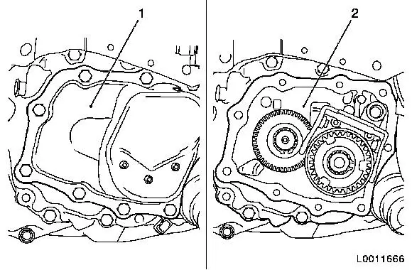
Remove gearbox cover (1)
Note: For F17+
transmission.
Remove gearshift module (2)
Note: For F17+ MTA
transmission.
|
| 2. |
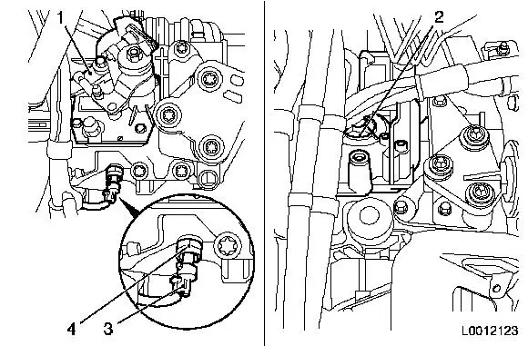
Remove reversing lamps switch (3).
| • |
Disconnect wiring harness plug, reversing lamp switch (4)
|
| • |
Unscrew reversing lamp switch
|
|
|
|
| 3. |
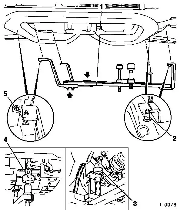
Attach KM-6001-B to front axle
body
Note: The guide pins
must sit in the support bearing with no play.
| • |
Release 2x bolt (arrows) for adjustment rails on KM-6001-B (1)
|
| • |
Insert KM-6001-B as shown
Note: 2x journals (2)
and (5) must sit flush in the guide holes of the front axle
body.
|
| • |
Tighten 2x bolt for adjustment rails
|
| • |
Twist up front support bearing (4)
| – |
until the guide pin is in contact with the front of the engine
damping block
|
|
| • |
Twist up rear support bearing (3)
| – |
until the guide pin is in contact with the rear of the engine
damping block
|
|
|
|
| 4. |
Remove front axle body
|
|
| 5. |
Remove end shield (1) cover 
|
|
|
| 8. |
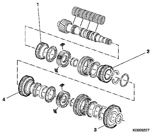
Check gears
Note: Replace damaged
components.
Gear wheel, 5th gear is removed and installed in the course of the
operation "End Shield, Dismantle and Assemble (F17+/F17+ MTA).
| 1. |
4th gear |
| 2. |
3rd gear |
| 3. |
1st gear |
| 4. |
2nd gear |
|
|
 Install
Important: Lubricate rotating
parts on their bearing, running, seating, and pressure surfaces
using transmission fluid. If a synchro body assembly has been
completely disassembled then the following method of procedure
shall be observed for assembly.
|
| 9. |
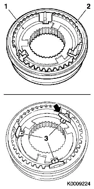
Assemble synchro body and shift sleeve
| • |
Insert synchro body (1) into shift sleeve (2).
|
| • |
Insert 3x thrust piece (3)
Note: Position at an
angle and then press into the synchro body assembly.
|
|
|
|
|
| 12. |
Install end shield (2)
|
| 13. |
Attach end shield cover (1)
|
|
| 14. |
Install front axle body
|
| 15. |
Detach KM-6001-B from front axle
body
|
|
| 16. |
Fit reversing lamp switch (3)
| • |
Tighten reversing lamp switch 20
Nm
|
| • |
Connect wiring harness plug (4) to reversing lamp switch
|
|
| 17. |
Install gearbox cover (1)
Note: For F17+
transmission.
Install gearshift module (2)
Note: For F17+ MTA
transmission.
|
|
|
