|
Main Shaft, Dismantle and Assemble (F17+/F17+
MTA)
Overview of Drive Shaft
Note: Transmission
remains installed.
 Remove Remove
|
| 1. |
Remove gearbox cover (1)
Note: For F17+
transmission.
Remove gearshift module (2)
Note: For F17+ MTA
transmission.
|
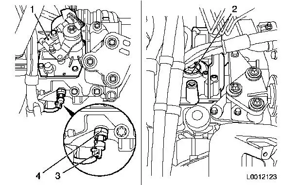
| 2. |
Remove reversing lamps switch (3).
| • |
Disconnect wiring harness plug, reversing lamp switch (4)
|
| • |
Unscrew reversing lamp switch
|
|
|
|
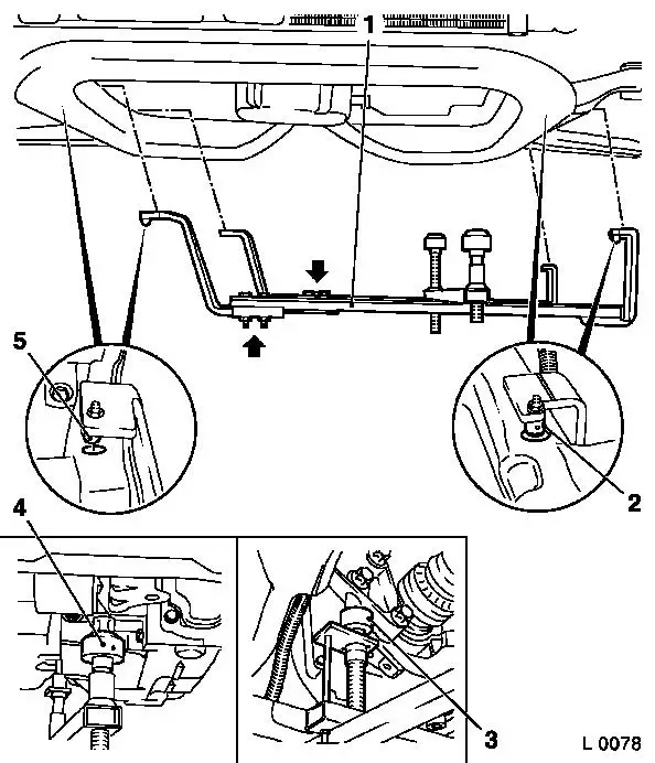
| 3. |
Attach KM-6001-B to front axle
body
Note: The guide pins
must sit in the support bearing with no play.
| • |
Release 2x bolt (arrows) for adjustment rails on KM-6001-B (1)
|
| • |
Insert KM-6001-B as shown
Note: 2x journals (2)
and (5) must sit flush in the guide holes of the front axle
body.
|
| • |
Tighten 2x bolt for adjustment rails
|
| • |
Twist up front support bearing (4)
| – |
until the guide pin is in contact with the front of the engine
damping block
|
|
| • |
Twist up rear support bearing (3)
| – |
until the guide pin is in contact with the rear of the engine
damping block
|
|
|
|
| 4. |
Remove front axle body
|
|
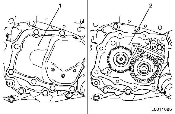
| 5. |
Remove end shield (1) cover 
|
|
|
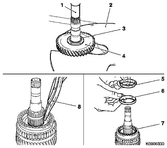
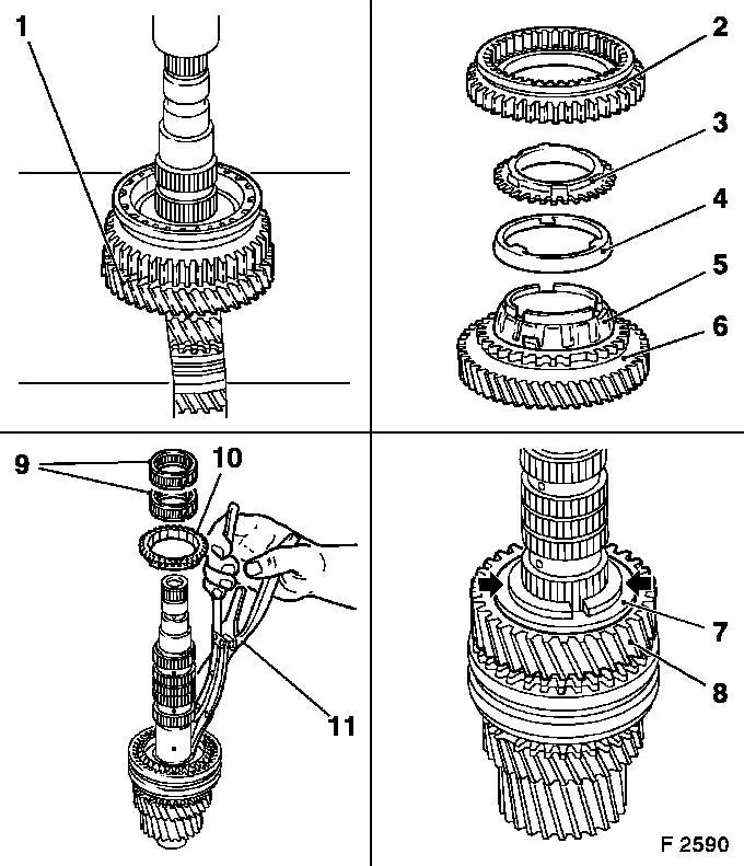
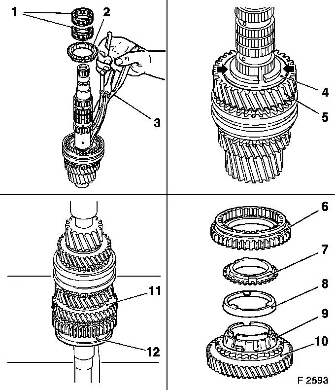
| 7. |
Detach 1st gear (4).
| • |
Press 1st gear off main shaft with KM-307-B (2) and KM-736
(1).
|
| • |
Remove gear wheel, 1st gear, and thrust washer (3)
|
|
| 8. |
Detach 3x synchroniser ring, gear wheel, 1st gear
| • |
Remove needle bearing, inner synchroniser ring (5),
intermediate ring (6) and outer synchroniser ring (7)
|
|
| 9. |
Remove synchro body retaining ring
| • |
Remove retaining ring synchro body 1st/2nd gear using KM-396 (8)
|
|
|
|
| 10. |
Detach 2nd gear
| • |
Press synchro body assembly 1st/2nd gear and gear wheel for 2nd
gear (1) off main shaft with KM-307-B and
KM-736
|
| • |
Remove shift sleeve 1st/2nd gear (2), outer synchro ring (3).
intermediate ring (4) and inner synchro ring (5) from gear wheel of
2nd gear (6) and needle bearing
|
|
| 11. |
Detach thrust washer halves (arrows)
| • |
Remove retaining ring (7)
|
| • |
Detach thrust washer halves
|
|
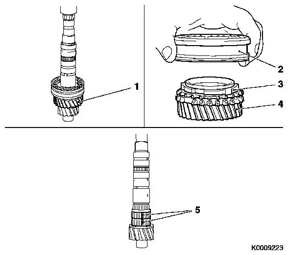
| 12. |
Remove 3rd gear gearwheel (8)
|
| 13. |
Remove retaining ring synchro body 3rd/4th gear
| • |
Remove 2x slotted needle bearings (9)
|
| • |
Remove 3rd gear (10) synchroniser ring
|
| • |
Remove retaining ring synchro body 3rd/4th gear using KM-396 (11)
|
| • |
Remove spacing ring from synchro body
|
|
|
|
| 14. |
Detach 4th gear
| • |
Press off gear wheel, 4th gear (4), and synchro body with KM-307-B
|
| • |
Remove synchro body 3rd/4th gear assembly (2), synchro ring 4th
gear (3) from 4th gear
|
|
| 15. |
Detach needle bearing (5)
| • |
Remove 2x slotted needle bearings from main shaft
Note: Open needle
bearing
|
|
|
Important: If gears are damaged,
always check the gears of the gear cluster and replace gear cluster
if necessary.
|
| 17. |
Check all parts for damage
Note: Replace damaged
components.
|
 Install
Important: Lubricate rotating
parts on their bearing, running, seating, and pressure surfaces
using transmission fluid. If a synchro body assembly has been
completely disassembled then the following method of procedure
shall be observed for assembly.
|
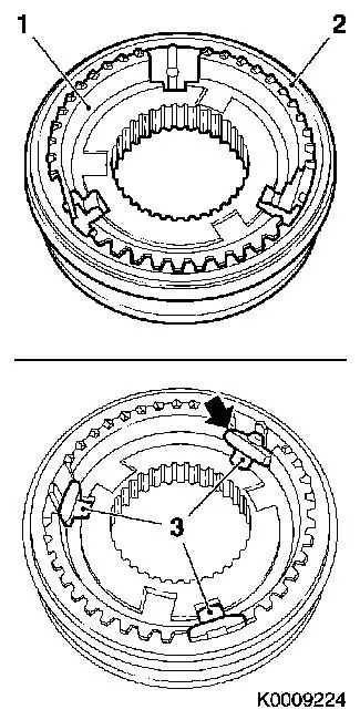
| 18. |
Assemble synchro body
| • |
Insert synchro body (1) into shift sleeve (2).
|
| • |
Insert 3x thrust piece (3)
Note: Position at an
angle and then press into the synchro body assembly.
|
|
|
|
|
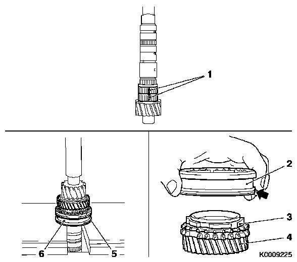
| 19. |
Fit needle bearing (1)
| • |
Place 2x slotted needle bearing on main shaft and clip
together
|
|
Important: Synchroniser ring lugs
must be aligned with synchro body grooves.
|
| 20. |
Attach synchro body assembly 3rd/4th gear
| • |
Position 4th gear synchro ring (3) and synchro body assembly
(2) on 4th gear (4).
Note: Groove on slider
sleeve (arrow) points to 4th gear.
|
| • |
Press synchro body assembly (6) and 4th gear (5) on to main
shaft
|
|
|
|
| 21. |
Fit 3rd gear
| • |
Locate spacing ring on synchro body
|
| • |
Attach retaining ring with KM-396
(3)
Note: Use new retaining
ring.
Retaining ring must sit in groove correctly.
|
| • |
Locate synchroniser ring 3rd gear (2) on synchro body
assembly
|
| • |
Attach 2x slotted needle bearings (1) to main shaft.
|
| • |
Locate 3rd gear (5) on main shaft
|
| • |
Fit both halves of the thrust washer (arrows) and retaining
ring (4) using grease
|
|
Important: Lugs of the synchro
rings must be flush with the grooves of the synchro body and the
gear wheel.
|
| 22. |
Attach synchro body assembly 1st/2nd gear
| • |
Place needle bearing on main shaft
|
| • |
Locate synchro body 1st/2nd gear (6) with inner synchro ring
(9), intermediate ring (8) and outer synchro ring (7) on gear wheel
for 2nd gear (10)
|
| • |
Press synchro body assembly 1st/2nd gear (12) on to main shaft
with 2nd gear (11)
|
|
|
|
| 23. |
Secure synchro body assembly 1st/2nd gear (3)
| • |
Insert new retaining ring (1) using KM-396 (2)
Note: Retaining ring
must sit in groove correctly.
|
|
| 24. |
Attach 1st gear (5)
| • |
Locate slotted needle bearing (6) on main shaft
|
Important: Lugs of the synchro
rings must be flush with the grooves of the synchro body and the
gear wheel.
|
| • |
Locate 1st gear with inner synchro ring (9), intermediate ring
(8) and outer synchro ring (7) on synchro body assembly 1st/2nd
gear (10)
|
|
| 25. |
Fit thrust washer 1st gear (4)
| • |
Press thrust washer onto main shaft (11) using KM-307-B
|
|
|
| 26. |
Visually check main shaft
Note: All gears must
turn freely.
|
|
| 28. |
Install end shield (2)
|
| 29. |
Attach end shield cover (1)
|
|
| 30. |
Install front axle body
|
| 31. |
Detach KM-6001-B from front axle
body
|
|
| 32. |
Fit reversing lamp switch (3)
| • |
Tighten reversing lamp switch 20
Nm
|
| • |
Connect wiring harness plug (4) to reversing lamp switch
|
|
| 33. |
Install gearbox cover (1)
Note: For F17+
transmission.
Install gearshift module (2)
Note: For F17+ MTA
transmission.
|
|
|
