|
End plate, dismantle and reassemble (F13+/F13+
MTA)
Note: Transmission
remains installed.
Overview end plate
 Remove Remove
|
| 2. |
Install end plate on KM-552 (2)
|
| 3. |
Install end plate with KM-552 on
KM-113-2 (1)
|
|
| 4. |
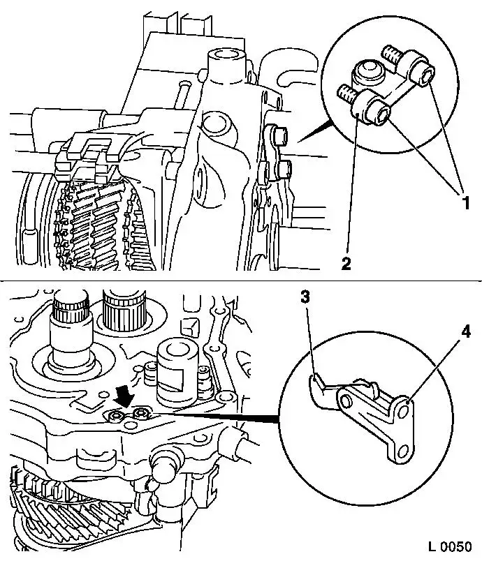
Remove bearing block (1) with rocker arm (2) from end plate
Note: Microencapsulated
screws. If the screws do not move easily, heat the end plate using
industrial heat gun to approx. 80°C.
|
|
|
|
| 5. |
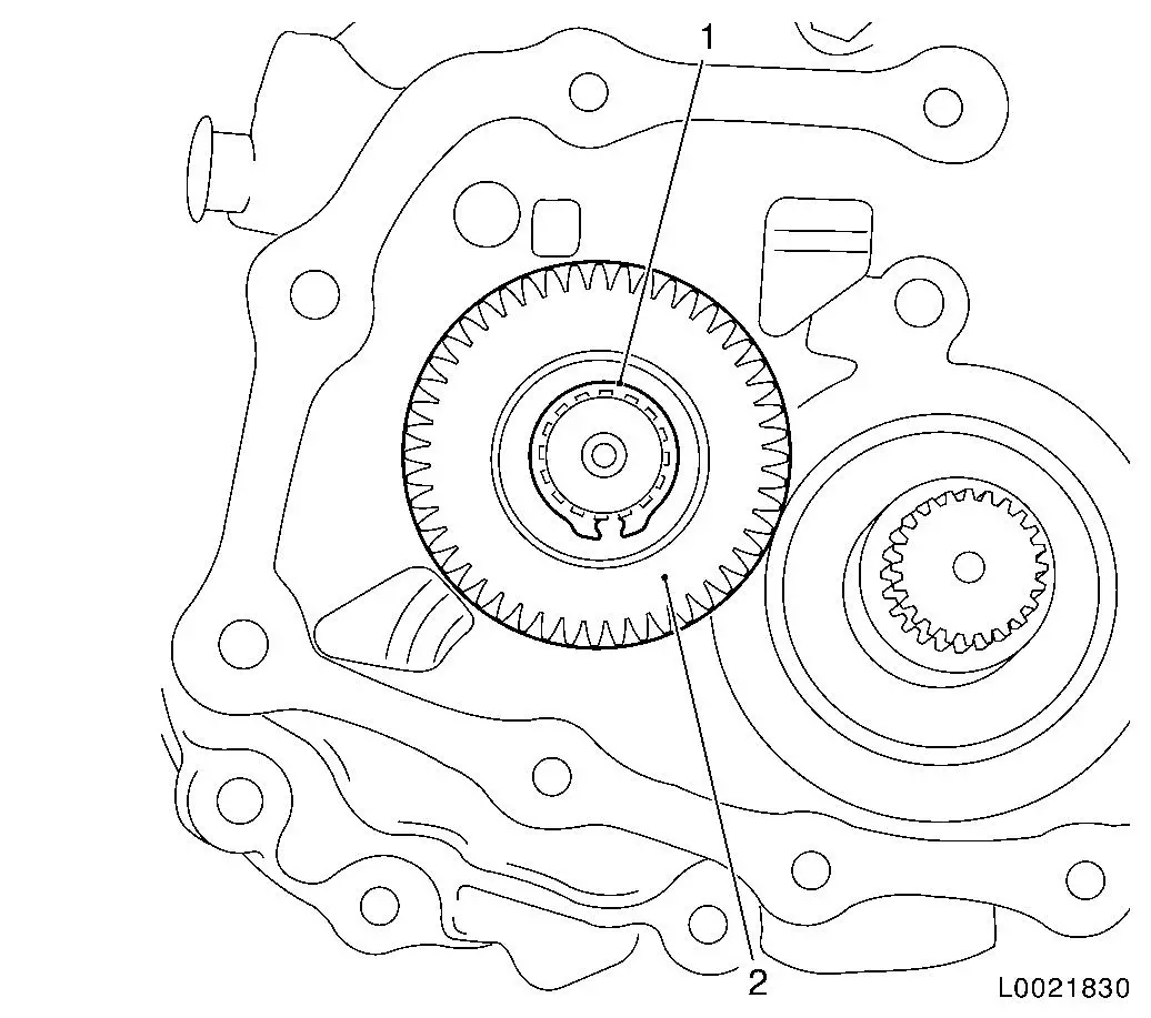
Remove gear wheel 5th gear (driven)
| • |
Remove lock ring from synchroniser body (1)
|
| • |
Remove gear wheel 5th gear and synchroniser body 5th gear with
KM-161-B (2) from main shaft
|
| • |
Remove 2x needle bearings for gear wheel 5th gear
|
|
|
| 6. |
Remove pressure disc (1) and 2x split shell (2)
|
|
|
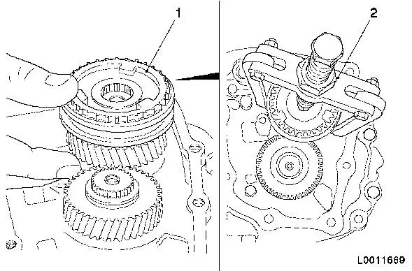
|
| 7. |
Remove lock ring (1) from gear wheel 5th gear (driving (2)
|
|
|
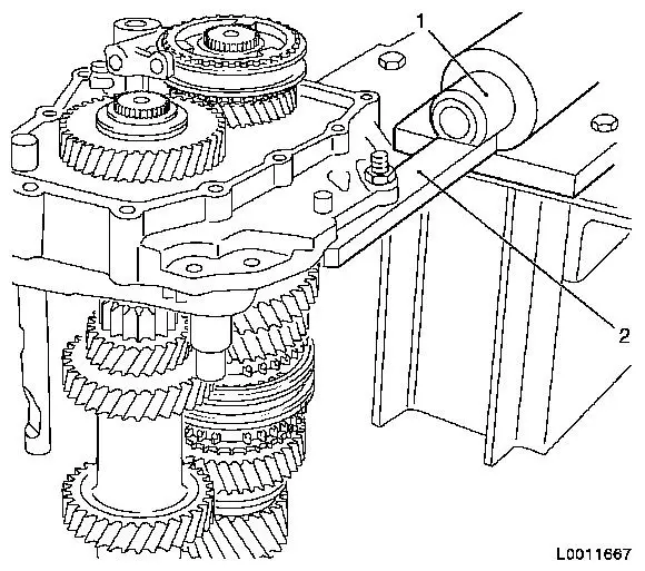
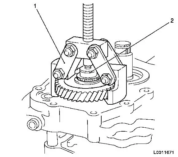
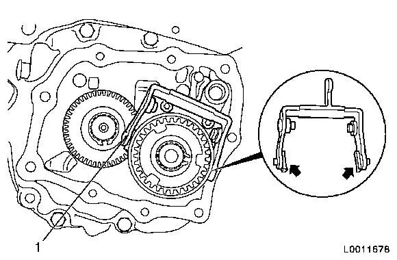
| 8. |
Remove gear wheel 5th gear (driving) with KM-553-A (1) from drive shaft
Note: Note correct
seating of KM-553-A on gear wheel 5th
gear (driving).
| • |
Place thrust piece (2) for KM-553-A
on drive shaft
|
|
|
|
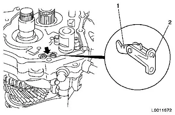
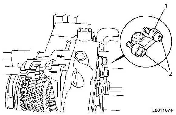
| 9. |
Remove bearing block (2) with pawl (1) from end plate
| • |
Unscrew 2x screw (arrow)
Note: Microencapsulated
screws. If the screws do not move easily, heat the end plate using
industrial heat gun to approx. 80°C.
|
|
|
|
| 10. |
Remove 4x locking plug (arrow) from end plate
| • |
Remove locking plug with KM-727 (2)
and KM-328-B (1)
|
|
|
|
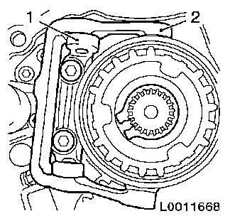
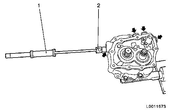
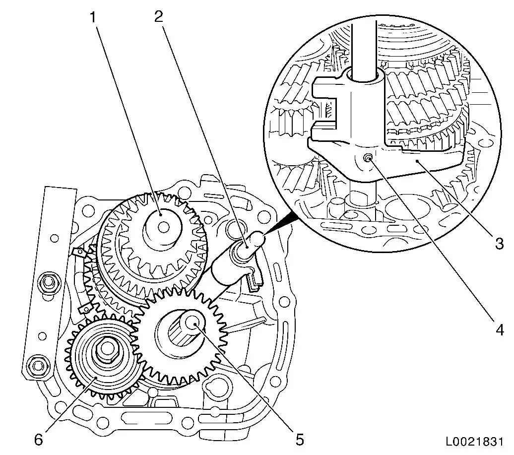
| 11. |
Remove bridge (1) for locking bolt from end plate
| • |
Engage 5th gear (arrow pointing right)
|
| • |
Unscrew 2x screw (2)
Note: Microencapsulated
screws. If the screws do not move easily, heat the end plate using
industrial heat gun to approx. 80°C.
|
| • |
Engage 2nd gear (arrow pointing left)
Note: When 2nd gear is
engaged, the bridge for the locking bolt springs out of the end
plate.
|
|
|
|
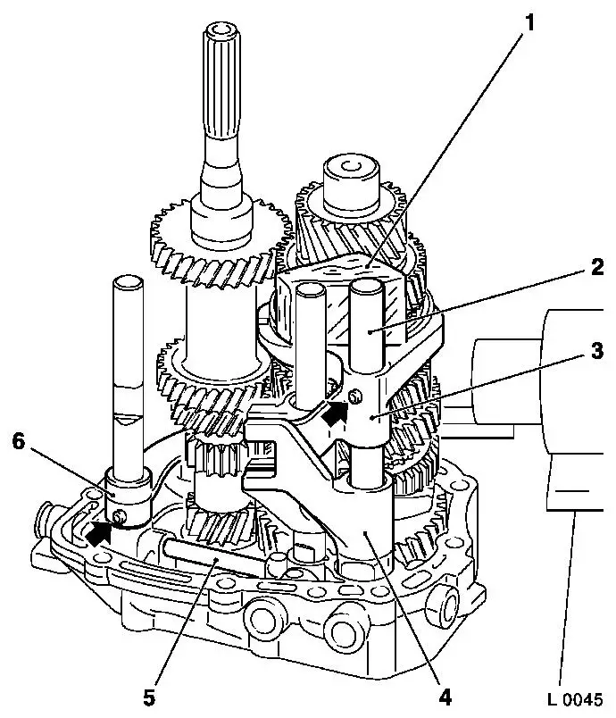
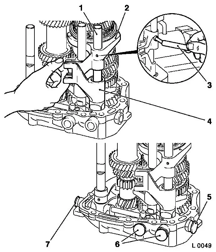
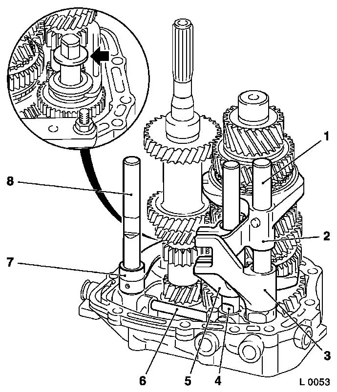
Important: Relieve load from
shift rod guide - to do this, prop top shift rods with wooden wedge
(1).
|
| 12. |
Remove shift fork 3rd/4th gear (3) and shift fork reverse gear
(6)
Note: Note installation
position.
| • |
Knock roll pins (arrow) out of shift fork 3rd/4th gear and
shift fork reverse gear with KM-308
|
| • |
Remove shift rod (2), shift rod reverse gear and shift fork
Note: Note installation
position.
|
|
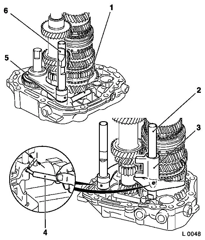
| 13. |
Remove shift driver 5th gear (4) from end plate
|
| 14. |
Remove locking bolt (5) for locking from end plate
|
|
|
| 15. |
Remove reverse gear wheel (6) from reverse gear wheel axle
|
| 16. |
Remove shift fork (3) with shift rod 1st/2nd gear (2) from end
plate
Note: Note installation
position.
| • |
Remove roll pin (4) with KM-308
|
|
Important: When knocking out the
main and drive shaft with mallet, ensure that the toothed gears of
the shafts do not touch or tilt.
Knock main and drive shaft out using mallet alternatingly.
|
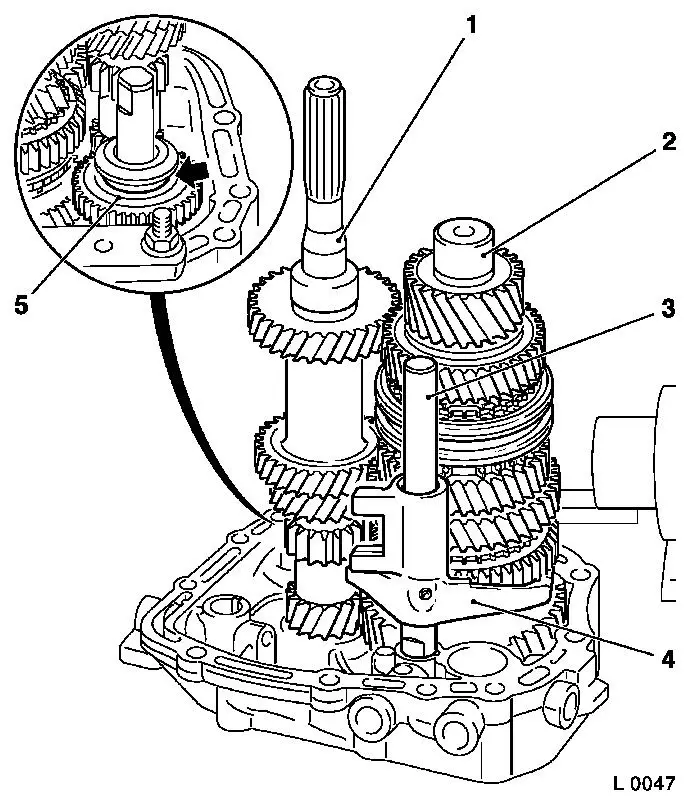
| 17. |
Press main shaft (1) out of end plate or knock out with
mallet
|
| 18. |
Press drive shaft (5) out of end plate or knock out with
mallet
|
|
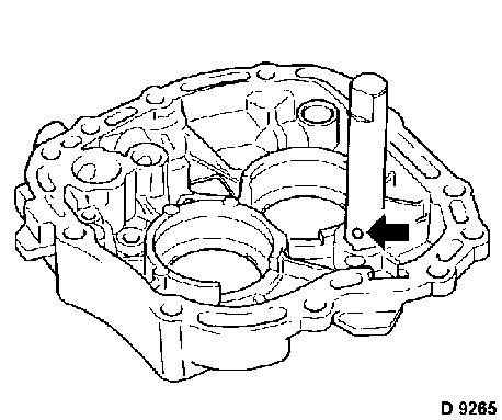
| 19. |
Remove reverse gear wheel axle from end plate
| • |
Tighten reverse gear wheel axle in vice with braces
|
| • |
Carefully knock end plate out with mallet
Note: Ensure that
locking ball (arrow) remains free.
|
|
|
|
|
| 20. |
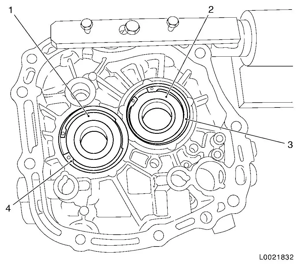
Remove drive shaft bearing (1) from end plate
| • |
Press bearing out with KM-500-5
|
|
| 21. |
Remove main shaft bearing (2) from end plate
| • |
Press bearing out with KM-500-5
|
|
|
| 22. |
Clean all parts and sealing surfaces
|
| 23. |
Check all parts for damage
Note: Replace damaged
parts.
|
 Install
| 24. |
Oil turning parts with transmission oil on their bearing,
running, seating or press surfaces
|
|
| 25. |
Install drive shaft bearing (1) in end plate
| • |
Press bearing in with KM-519
|
|
| 26. |
Install main shaft bearing (2) in end plate
| • |
Press bearing in with KM-373-1
|
|
|
Important: Note installation
position.
|
| 27. |
Press reverse gear wheel axle into end plate
| • |
Insert locking ball (arrow)
|
| • |
Press in reverse gear wheel axle up to stop
Note: Locking ball must
sit in groove of end plate
|
|
|
|
|
| 28. |
Insert reverse gear wheel (5) in end plate
Note: Reverse gear
wheel shift fork groove (arrow) points upward.
|
Important: Wet bearing and return
hole with transmission oil.
|
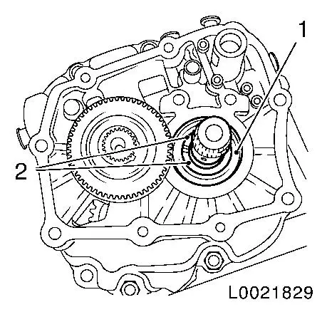
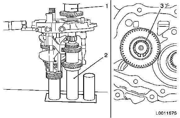
| 29. |
Press main shaft (2) and drive shaft (1) into end plate with
KM-6337 and KM-6338
Note: Note installation
position. Place main and drive shaft on KM-6337 .
|
| 30. |
Insert shift fork (4) with shift rod 1st/2nd gear (3) in end
plate
Note: Note installation
position.
|
|
|
| 31. |
Install locking bolt (1) reverse gear and 3rd/4th gear
|
| 32. |
Relieve load from shift rod guides in end plate
| • |
Support shift rods with wooden wedge during pin insertion
|
|
| 33. |
Install shift fork (5) and shift rod reverse gear (6)
| • |
Drive roll pin in with KM-308 (4)
Note: Allow new roll
pin to project approx. 2 mm
(dimension I).
|
|
| 34. |
Install roll pin for shift fork (3) and shift rod (2) 1st/2nd
gear
| • |
Drive roll pin in with KM-308 (4)
Note: Allow new roll
pin to project approx. 2 mm
(dimension I).
|
|
|
|
| 35. |
Install shift driver 5th gear (4)
|
| 36. |
Install shift fork (2) and shift rod 3rd/4th gear (1)
Note: Note installation
position.
| • |
Drive roll pin in with KM-308 (3)
Note: Allow new roll
pin to project approx. 2 mm
(dimension I).
|
|
| 37. |
Install 4x locking plug (5 - 7)
| • |
Drive locking plug in with mallet or soft metal driver up to
stop
|
|
| 38. |
Move shift fork to idle position
|
|
|
| 39. |
Install bridge (2) for locking bolt on end plate
| • |
Insert bridge for locking bolt
|
| • |
Screw in 2x new screw (1)
Note: Wet screws with
locking compound.
|
|
| 40. |
Change shift fork 1st/2nd gear to neutral
|
| 41. |
Tighten 2x screw bridge 7 Nm
|
| 42. |
Move shift fork to idle position
|
| 43. |
Install bearing block (4) on end plate with pawl (3)
| • |
Tighten 2x screw (arrow) 9 Nm
Note: Wet screws with
locking compound.
|
|
|
|
| 44. |
Remove end plate with KM-552 from
KM-113-2
|
Important: Long gear wheel hub
points to end plate.
|
| 45. |
Press gear wheel 5th gear (driving) (1) onto drive shaft with
KM-473
| • |
Insert end plate with main shaft and drive shaft in KM-554 (2)
|
| • |
Install new locking ring (3)
|
|
|
| 46. |
Install end plate with KM-552 on
KM-113-2
|
| 47. |
Insert pressure disc (1) and 2x split shell (2)
|
|
|
|
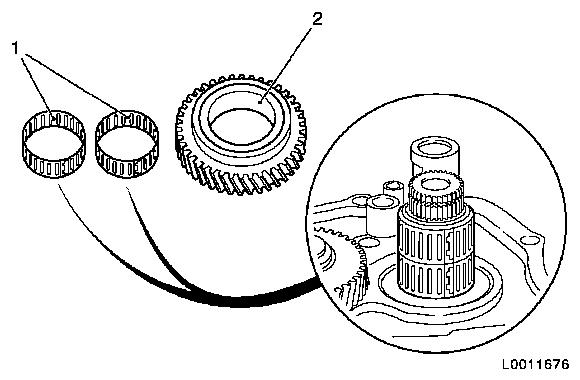
| 48. |
Install gear wheel 5th gear (driven) (2) on main shaft
| • |
Install 2x needle bearing (1) on main shaft
Note: Ensure correct
seating of split needle bearing.
| – |
Wet 2x needle bearing with transmission oil
|
|
|
|
|
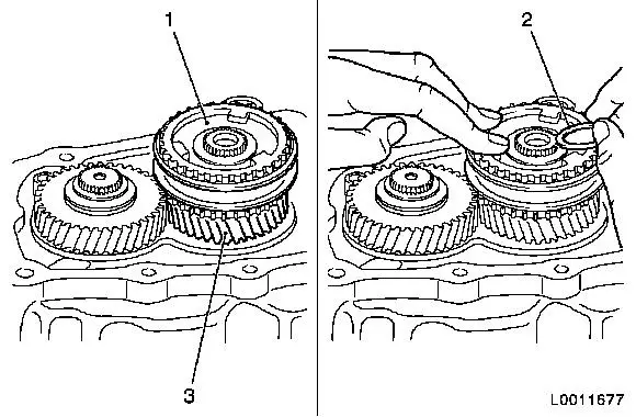
| 49. |
Press gear wheel 5th gear (driven) (3) and synchroniser body
(1) onto main shaft with KM-473
Note: Note installation
position. Tips of teeth of synchroniser sleeve of synchroniser body
point to end plate.
| • |
Wet seating surface of main shaft and synchroniser body with
transmission oil
|
| • |
Install new lock ring (2)
|
|
|
|
| 50. |
Insert 2x sliding block (arrows) in shift fork 5th gear
|
| 51. |
Install bearing block with rocker arm (1) on end plate
| • |
Tighten 2x new screw 22 Nm
Note: Insert screws
with locking compound.
|
|
|
|
| 52. |
Install thrust washer (arrow) on reverse gear wheel axle
Note: Bond thrust
washer with grease.
|
| 53. |
Conduct visual inspection for correct position and correct
seating
| 1. |
Shift rod 3rd/4th gear |
| 2. |
Shift fork 3rd/4th gear |
| 3. |
Shift driver 5th gear |
| 4. |
Shift rod 1st/2nd gear |
| 5. |
Shift fork 1st/2nd gear |
| 6. |
Locking bolt for gear retention |
| 7. |
Shift fork reverse gear |
| 8. |
Shift rod reverse gear |
|
| 54. |
Check gearshift function
Shift through all gears
|
|
|
| 55. |
Remove end plate from KM-113-2 (1)
and KM-552 (2)
|
|
|
