|
Transmission, Remove and Install (Z13DTH/M20
MTA)
Note: If the
transmission is replaced, the following parts must be
transferred:
| 1. |
Bracket, left engine damping block |
| 2. |
MTA system |
| 3. |
Transmission closure cap with gasket. The closure
cap gasket must be transferred on the old transmission. When
attaching the MTA system to the exchange transmission, a new gasket
must be used. |
 Remove Remove
Important: Before carrying out
any work on the M20-MTA transmission, it is essential that the MTA
system pressure (approx. 40-60 bar) is released.
|
| 1. |
Remove MTA system pressure
|
| 2. |
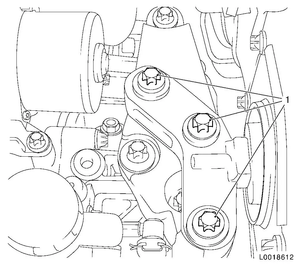
Remove battery support
|
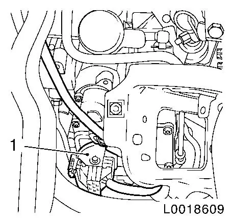
| 4. |
Detach battery wiring harness bracket (1) from MTA supply
unit
|
|

|
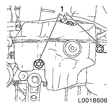
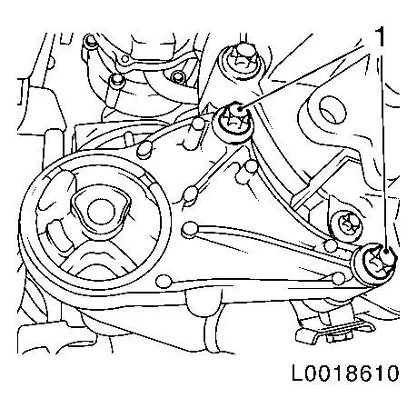
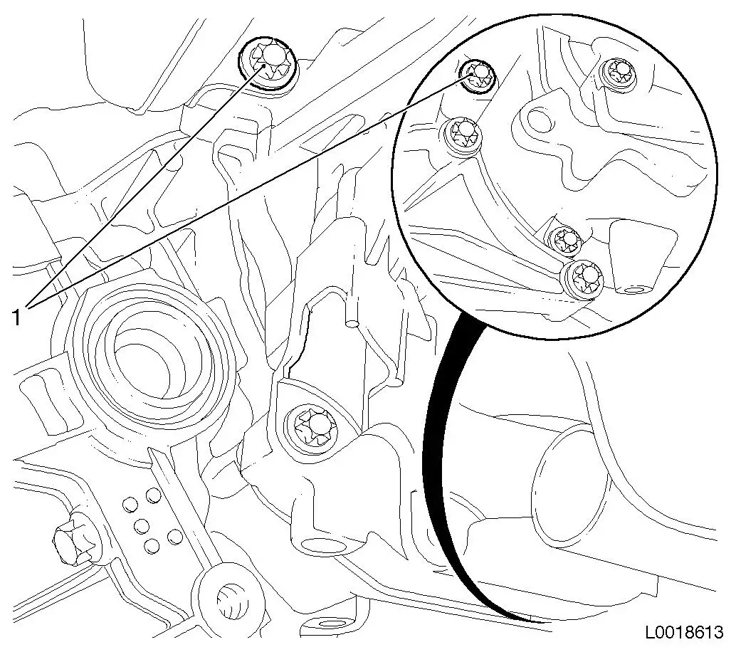
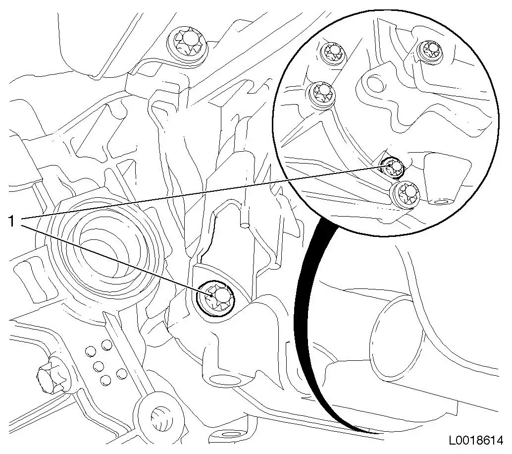
| 5. |
Release MTA system supply unit
| • |
Unscrew 3x bolt (1)
Note: Note differing
bolt lengths
|
|
|
|
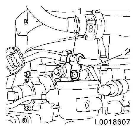
| 6. |
Release MTA wiring harness bracket (1)
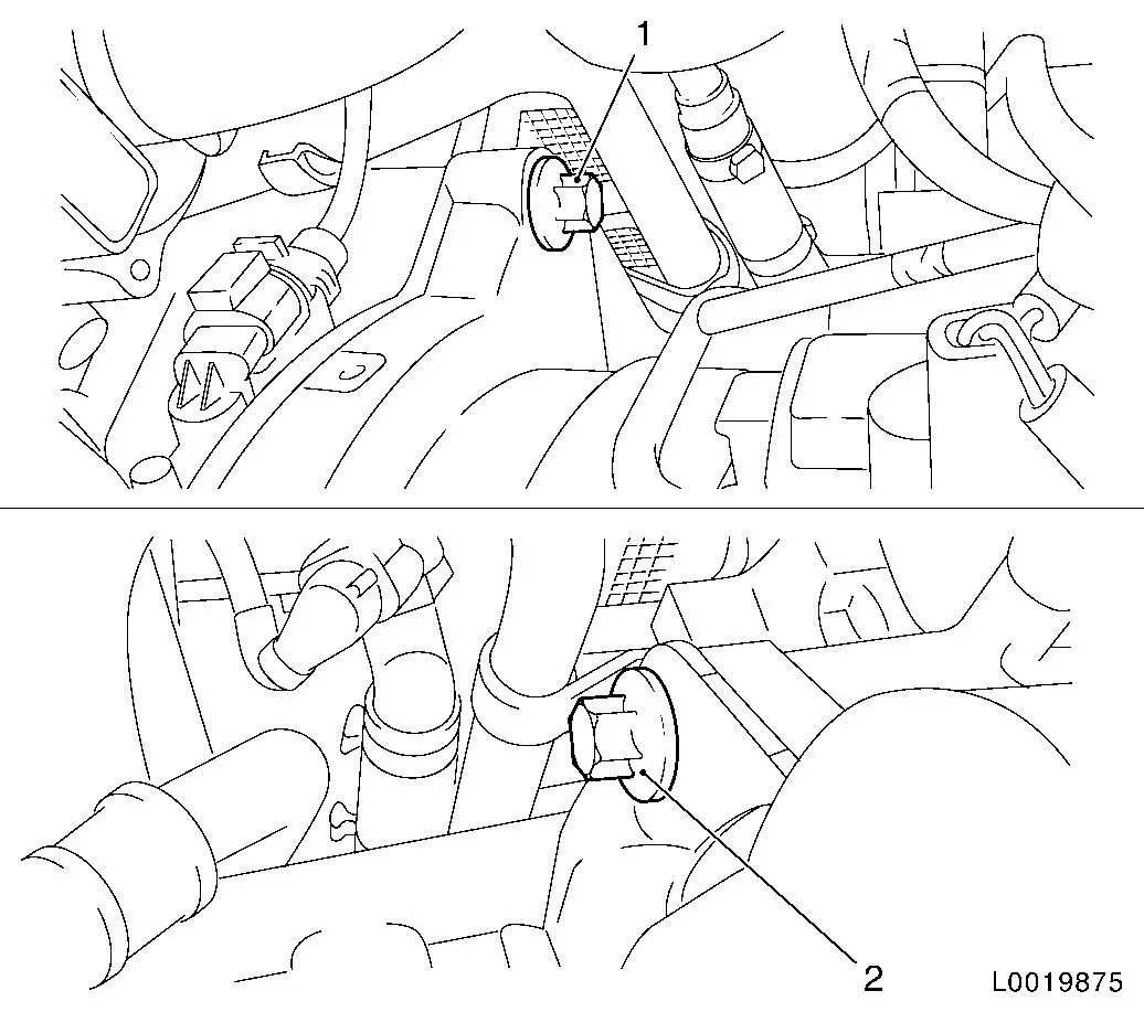
|
|
|
| 7. |
Disconnect MTA system wiring harness
| • |
Release wiring harness plug (1) and disconnect
|
|
|
|
| 8. |
Drain off transmission fluid
Note: Place collecting
pan underneath.
| • |
Unscrew drain plug
Note: Allow
transmission fluid to drain out for approx. 10 minutes.
|
| • |
Tighten new drain plug 20 Nm
|
|
|
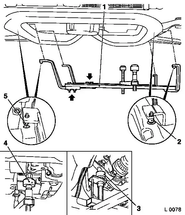
| 9. |
Attach KM-6001-B to front axle
body
| • |
Release 2x bolt (arrows) for adjustment rails on KM-6001-B (1)
|
| • |
Insert KM-6001-B as shown
Note: 2x journals (2)
and (5) must sit flush in the guide holes of the front axle
body.
|
| • |
Tighten 2x bolt for adjustment rails
|
| • |
Twist up front support bearing (4)
| – |
as far as the stop on the guide pin of the front engine damping
block
Note: The guide pins
must sit in the support bearings with no play.
|
|
| • |
Twist up rear support bearing (3)
| – |
as far as the stop on the guide pin of the rear engine damping
block bracket
Note: The guide pins
must sit in the support bearings with no play.
|
|
|
|
Important: KM-6001-B remains on front axle body and may not be
moved.
|
| 10. |
Remove front axle body
|
| 11. |
Detach right axle shaft from intermediate shaft 
| • |
Attach axle shaft to vehicle underbody
|
|
| 12. |
Remove intermediate shaft
Note: Fluid escapes.
Place pan underneath.
|
| 13. |
Remove left axle shaft
| • |
Attach axle shaft to vehicle underbody
|
|
| 14. |
Remove front engine damping block
|
|
|
|
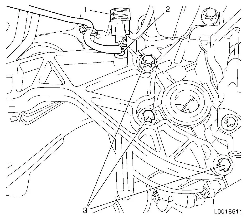
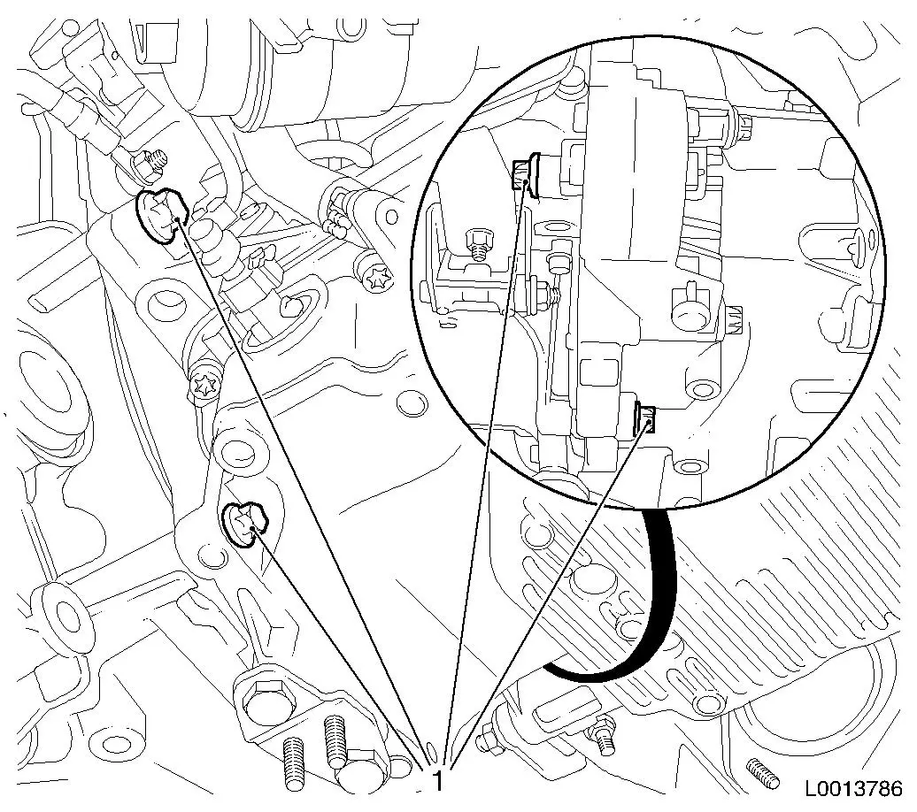
| 15. |
Remove rear engine damping block
| • |
Release wiring harness plug (1) and disconnect
|
| • |
Unscrew bolt (2) from wiring harness bracket
|
|
|
|
| 16. |
Detach left engine damping block from engine damping block
bracket
|
|
Important: Do not damage wiring
harnesses and attaching parts
Pay attention to the vacuum line on the throttle valve module.
|
| 17. |
Lower the engine and transmission on the left-hand side approx.
20 centimetres
|
|
| 19. |
Release transmission at top
Note: With the vehicle
raised, release the upper transmission bolts from below.
| • |
Unscrew the front (1) and rear (2) upper transmission bolts
|
|
|
|
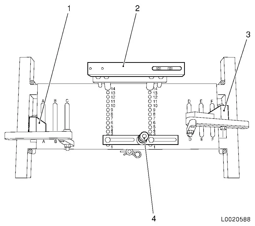
| 20. |
Place transmission holder DT-47648 on
KM-904 and preinstall as shown in the
illustration:
|
Component
|
Position on base plate
|
Designation
|
|
DT-47648-2
(4)
|
2
|
Clutch housing support
|
|
DT-47648-3
(2)
|
14
|
Transmission housing support
|
|
DT-47648-5 left
(1)
|
A
|
Support with rear transmission swivel arm
|
|
DT-47648-5 right
(3)
|
F
|
Support with front transmission swivel arm
|
|
|
Important: It is essential to
follow the manufacturer's instructions for transmission holder
DT-47648 .
|
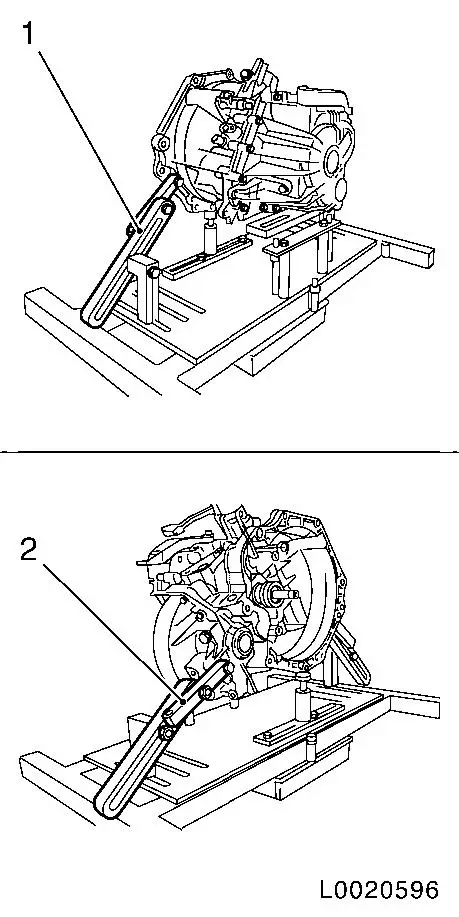
| 21. |
Attach DT-47648 to transmission
Note: Before placing in
position, slacken all bolt connections of the swivel arms and
supports as far as the base plate. Adjust the supports using the
spindles until they are as low as possible.
| • |
Place DT-47648 with supports in
position under the transmission
|
| • |
Tighten bolt connections of the supports
|
| • |
Attach swivel arm (1) and (2) to transmission
|
| • |
Tighten bolt connections of the swivel arms starting from the
transmission and going as far as the base plate
Note: Align the swivel
arms so that as little leverage as possible is created.
|
|
|
|
|
| 22. |
Remove transmission
| • |
Press transmission off engine and slowly lower the hydraulic
jack
Note: Do not damage
wiring harnesses and attaching parts
|
|
|
Important: Do not damage
attaching parts when putting the transmission down.
|
| 23. |
Detach transmission from transmission holder DT-47648
Note: 2nd mechanic
required.
| • |
Put transmission down carefully
|
|
|
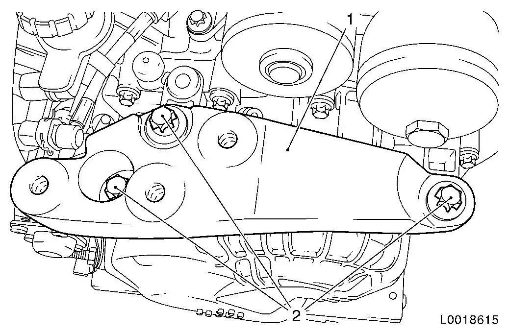
| 24. |
Detach left engine damping block bracket (1) from
transmission
Note: Only required if
the transmission is being exchanged.
|
|
 Install
|
| 25. |
Attach left engine damping block bracket (1) to
transmission
Note: Only required if
the transmission is being exchanged.
| • |
Tighten 3x bolt (2) 60 Nm
|
|
|
| 26. |
Attach transmission to transmission holder DT-47648
Note: 2nd mechanic
required.
|
| 27. |
Install transmission with DT-47648
| • |
Raise transmission and align it
|
| • |
Place transmission so that it is in even contact with the
engine
Note: Ensure it is
seated perfectly.
|
|
|
| 28. |
Fasten transmission at the bottom
| • |
Tighten 2x bolt M12 (1)
|
|
|
| 29. |
Detach transmission holder DT-47648
from transmission
| • |
Lower hydraulic jack with transmission holder DT-47648 and extend
|
|
|
| 30. |
Fasten transmission at the bottom
| • |
Tighten 2x bolt M10 (1) 40 Nm
Note: Note differing
bolt lengths
|
|
|
|
| 31. |
Fasten transmission at top
Note: With the vehicle
raised, fasten the upper transmission bolts from below.
| • |
Tighten the front (1) and rear (2) M12 upper transmission bolts
60 Nm
|
|
|
Important: Do not damage wiring
harnesses and attaching parts
Pay attention to the vacuum line on the throttle valve module.
|
| 32. |
Raise engine and transmission on the left hand side
|
|
| 33. |
Attach the left engine damping block to the left engine damping
block bracket
| • |
Screw in 3 bolts (1) loosely
|
|
|
| 34. |
Attach left axle shaft
|
| 35. |
Install intermediate shaft
|
| 36. |
Attach right axle shaft to intermediate shaft
|
| 37. |
Install front engine damping block
| • |
Tighten 2x bolt (1) 80 Nm
|
|
|
|
|
| 38. |
Install rear engine damping block
| • |
Fasten wiring harness bracket
|
| • |
Connect and lock wiring harness plug (1)
|
|
|
| 39. |
Install front axle body
Note: Do not install
front exhaust pipe and central silencer yet.
|
|
| 40. |
Fasten left engine damping block
| • |
Tighten 3x bolt (1) 55 Nm
|
|
|
| 41. |
Detach engine bridge in conjunction with MKM-883-1-A and MKM-883-2
|
| 42. |
Detach KM-6001-B from front axle
body
|
| 43. |
Install exhaust system
|
| 44. |
Connect wiring harness, MTA-system
| • |
Connect and lock wiring harness plug (1)
|
|
|
|
| 45. |
Fasten MTA wiring harness bracket (2)
|
|
|
| 46. |
Fasten MTA system supply unit
| • |
Tighten 3x bolt (1) 10 Nm
Note: Note differing
bolt lengths
|
|
|
|
| 47. |
Attach battery wiring harness bracket (1) to MTA system supply
unit
|
|
|
| 48. |
Top up with transmission fluid
|
| 49. |
Install battery.
| • |
Install battery support
|
|
| 50. |
Fill coolant. Adjust level if necessary.
|
| 51. |
Program volatile memories
|
| 53. |
Necessary Start-Up Routines for Easytronic
|
| 54. |
Work to be carried out with Tech 2
|
|
