|
Steering Column Assembly, Remove and Install
Note: Before
installation work affecting the airbag, follow the safety
instructions for the pyrotechnic systems.
 Remove Remove
| 1. |
Lock steering
| • |
Turn steering into straight-ahead position
|
| • |
Allow steering lock to engage
|
|
| 2. |
Remove footwell trim driver's side
|
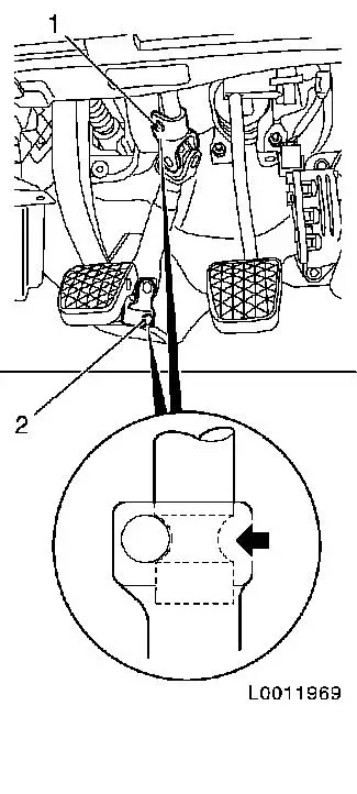
| 3. |
Remove 2x clamp bolt (1) and (2)
Note: Note installation
position of clamp bolts.
|
| 4. |
Compress intermediate shaft slightly and remove
|
|
|
| 5. |
Disconnect ground cable from battery
Note: Wait 1 minute for
the capacitor to discharge
|
| 6. |
Remove airbag unit
Note: The airbag unit
must not be forced open and must always be laid with the cushion
side facing upwards.
|
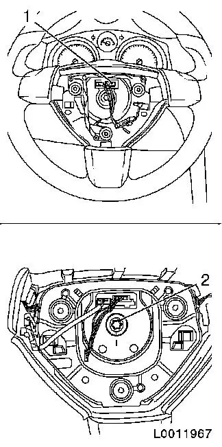
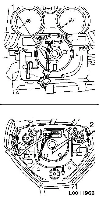
| 7. |
Separate wiring harness plug (1) for horn / infotainment
|
| 8. |
Remove steering wheel from steering column assembly
| • |
Remove steering wheel from steering shaft
|
|
|
|
| 9. |
Remove top steering column trim
| • |
Unclip 2x from instrument
|
|
| 10. |
Remove lower steering column trim
|
| 11. |
Remove CIM module
| • |
Separate wiring harness plug
|
|
| 12. |
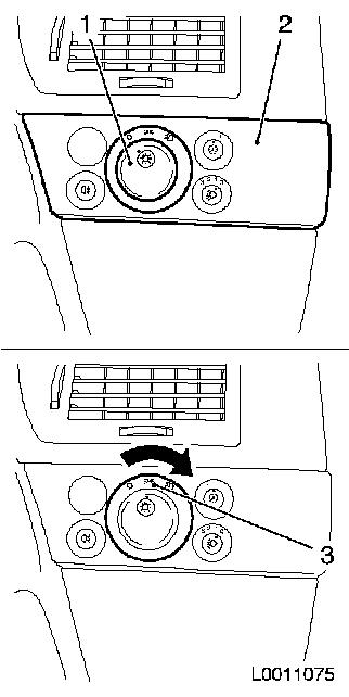
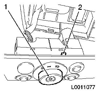
Release light switch unit
Note: To release the
light switch unit, press in the rotary knob (1) in position "0",
move the pressed in knob to the centre position (3), light switch
unit (2) is released.
|
|
|
| 13. |
Withdraw light switch unit
|
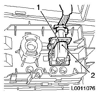
| 14. |
Separate wiring harness plug for light switch unit
| • |
Separate wiring harness plug
| – |
Press down secondary fuse (2)
|
|
|
|
|
| 15. |
Remove lower instrument panel padding trim
| • |
Remove lower instrument panel padding trim
|
|
| 16. |
Remove wiring harness from steering column assembly
| • |
Unclip wiring harness from holder
|
|
| 17. |
Remove steering column assembly from steering crossmember
Note: Note installation
position of locking pin on top of steering column
|
 Install
| 18. |
Attach steering column assembly to steering crossmember
| • |
Insert steering column assembly
Note: Locking pin must
sit correctly in steering crossmember
|
|
| 19. |
Attach wiring harness to steering column assembly
| • |
Clip wiring harness into holder
|
|
| 20. |
Lock steering
| • |
Turn steering column to straight-ahead position
| – |
Marking on steering column points down
|
|
| • |
Allow steering lock to engage
|
|
| 21. |
Install lower instrument panel padding trim
| • |
Install lower instrument panel padding trim
|
|
| 22. |
Connect wiring harness plug for light switch unit
|
| 23. |
Install light switch unit
|
| 24. |
Release light switch unit
Note: Turn rotary
switch (1) to position "0", light switch lock (2) projects.
|
|
|
| 25. |
Install CIM module
| • |
Connect wiring harness plug
|
|
| 26. |
Install lower steering column trim
|
| 27. |
Install upper steering column trim
| • |
Clip in 2x on instrument
|
|
| 28. |
Guide airbag (1) wiring harness through opening in steering
wheel hub
|
| 29. |
Attach steering wheel to steering shaft
| • |
Place steering wheel on steering column assembly
Note: Ensure that the
marks (2) on the steering wheel and steering shaft align
|
| • |
Screw in bolt 30 Nm
Note: Clean thread and
fit new bolt with locking compound
|
|
|
|
| 30. |
Connect wiring harness plug for horn / infotainment
|
| 32. |
Attach intermediate shaft to steering shaft 24 Nm
| • |
Slide intermediate shaft onto steering shaft
|
| • |
Attach clamp bolt (1)
Note: Before inserting
the clamp bolt make certain that steering shaft groove (arrow) is
flush with the bore in the intermediate shaft.
Clean thread and insert bolt with locking compound.
Note installation position of clamp bolt
|
|
| 33. |
Attach intermediate shaft to steering gear 24 Nm
| • |
Slide intermediate shaft (2) onto steering gear
Note: Ensure that the
wheels are in the straight ahead position
|
| • |
Attach clamp bolt
Note: Before inserting
the clamp bolt make certain that steering gear shaft groove (arrow)
is flush with the bore in the intermediate shaft.
Clean thread and insert bolt with locking compound.
|
|
| 34. |
Install footwell trim
|
| 35. |
Check straight-ahead position, adjust if necessary 
|
|
|
| 36. |
Connect ground cable to battery.
|
|
