Brake Rotor Assembled Lateral Runout Measurement
Special Tools
| • |
CH-41013 Rotor
Resurfacing Kit |
| • |
CH-42450-A
Wheel Hub Resurfacing Kit |
| • |
CH-45101 Hub
and Wheel Runout Gauge |
| • |
CH-45101-100
Conical Brake Rotor Washers |
For equivalent regional tool, refer to
Special Tools .
|
Note:
| • |
Brake rotor
assembled lateral runout (LRO) exceeding the maximum allowable
specification can cause thickness variation to develop in the brake
rotor over time, usually between 4,800 and 11,300 km (3,000
and 7,000 mi) . |
| • |
Brake rotor
thickness variation MUST be checked BEFORE checking for assembled
lateral runout (LRO). Thickness variation exceeding the maximum
acceptable level can cause brake pulsation. Refer to
Brake Rotor Thickness Variation Measurement . |
|
| 1. |
Match mark the position of the
brake rotor to the wheel studs if this has not been done
already. |
|
Note: Whenever the
brake rotor has been separated from the hub/axle flange, any rust
or contaminants should be cleaned from the hub/axle flange and the
brake rotor mating surfaces. Failure to do this may result in
excessive assembled lateral runout (LRO) of the brake rotor, which
could lead to brake pulsation.
|
| 2. |
Inspect the mating surface of
the hub/axle flange and the brake rotor to ensure that there are no
foreign particles, corrosion, rust, or debris remaining. If the
wheel hub/axle flange and/or if the brake rotor mating surfaces
exhibit these conditions, perform the following steps: |
| |
2.2 |
Using the CH-42450-A
resurfacing kit , thoroughly clean any rust or corrosion
from the mating surface of the hub/axle flange. |
| |
2.3 |
Using the CH-41013
resurfacing kit , thoroughly clean any rust or corrosion
from the mating surface of the brake rotor. |
| |
2.4 |
Clean the friction surfaces of
the brake rotor with denatured alcohol, or an equivalent approved
brake cleaner. |
| 3. |
Install the rotor to the
hub/axle flange using the matchmark made prior to removal.
|
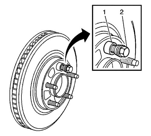
| 4. |
Hold the rotor firmly in place
against the hub/axle flange and install one of the
CH-45101-100 washers (1), and one lug nut (2) onto
the upper-most wheel stud. |
| 5. |
Continue to hold the rotor
secure and tighten the lug nut firmly by hand. |
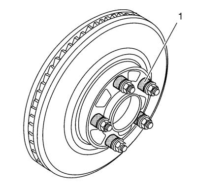
| 6. |
Install the remaining
CH-45101-100 washers (1) and lug nuts onto the
wheel studs and tighten the nuts firmly by hand in a
star-pattern. |
| 8. |
If the brake rotor has been
REFINISHED or REPLACED with a new rotor, proceed to step 14.
|
| 9. |
If the brake rotor meets the
following criteria, proceed to step 10. |
| |
• |
The rotor is within
specifications and is being REUSED. |
| |
• |
The rotor has NOT been
refinished. |
| |
• |
The rotor does NOT exhibit
thickness variation exceeding the maximum allowable level.
|
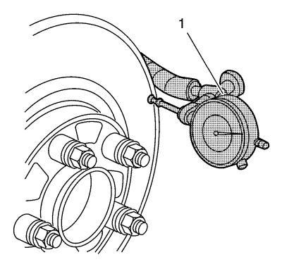
| 10. |
Mount the CH-45101
gauge (1) or equivalent, to the strut and position the
indicator button so it contacts the brake rotor friction surface at
a 90 degree angle, approximately 13 mm (0.5
in) from the outer edge of the rotor. |
| 11. |
Measure and record the
assembled LRO of the brake rotor. |
| |
11.1 |
Rotate the rotor until the
lowest reading is displayed on the indicator dial, then set the
dial to zero. |
| |
11.2 |
Rotate the rotor until the
highest reading is displayed on the dial. |
| |
11.3 |
Mark the location of the high
spot relative to the nearest wheel stud, or studs. |
| |
11.4 |
Measure and record the amount
of LRO. |
| 12. |
Compare the brake rotor
assembled LRO to the disc brake component specifications.
|
| 13. |
If the brake rotor assembled
LRO is within specifications, proceed to step 18. |
| |
If the brake rotor assembled LRO exceeds the specification,
refinish the rotor to ensure true parallelism. Refer to
Brake Rotor Refinishing . After refinishing the rotor, proceed
to step 14. |
| 14. |
Mount the CH-45101
gauge (1) or equivalent, to the strut and position the
indicator button so it contacts the brake rotor friction surface at
a 90 degree angle, approximately
13 mm (0.5 in) from the outer edge of the
rotor. |
| 15. |
Measure and record the
assembled LRO of the brake rotor. |
| |
15.1 |
Rotate the rotor until the
lowest reading is displayed on the indicator dial, then set the
dial to zero. |
| |
15.2 |
Rotate the rotor until the
highest reading is displayed on the dial. |
| |
15.3 |
Mark the location of the high
spot relative to the nearest wheel stud, or studs. |
| |
15.4 |
Measure and record the amount
of LRO. |
| 16. |
Compare the brake rotor
assembled LRO to the disc brake component specifications.
|
| 18. |
If the brake rotor assembled
LRO measurement is within specification, install the brake calliper
and depress the brake pedal several times to secure the rotor in
place before removing the CH-45101-100 washers
. |
|
