Vacuum Pump Assembly Replacement (1.7L Diesel LPL, LPV, and
LUB)
Removal Procedure
| 3. |
Unclip the electronic control
module bracket and move the engine control module to one
side. |
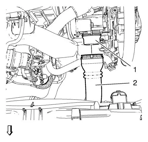
| 6. |
Disconnect the charge air
cooler outlet air hose (2) from the throttle body (1). |
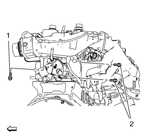
| 7. |
Remove the 3 intake manifold
bracket bolts (1, 2). |
| 8. |
Remove the 3 front intake
manifold bolts (2). |
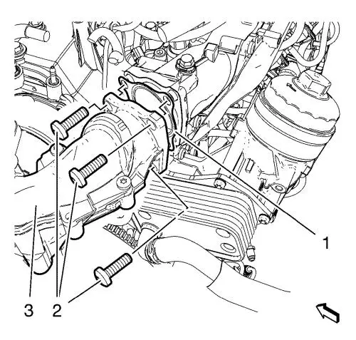
| 9. |
Remove the front intake
manifold (3). |
| 10. |
Remove and DISCARD the front
intake manifold gasket (1). |
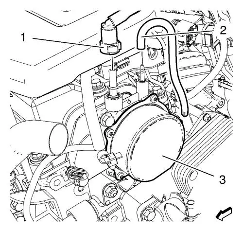
| 12. |
Install the negative pressure
hose (2). |
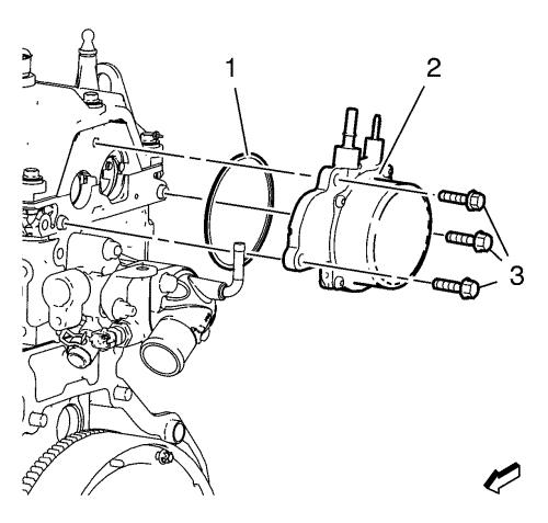
| 13. |
Remove the 3 vacuum pump bolts
(3). |
| 14. |
Remove the vacuum pump
(2). |
| 15. |
Remove and DISCARD the vacuum
pump seal ring (1). |
Installation Procedure
|
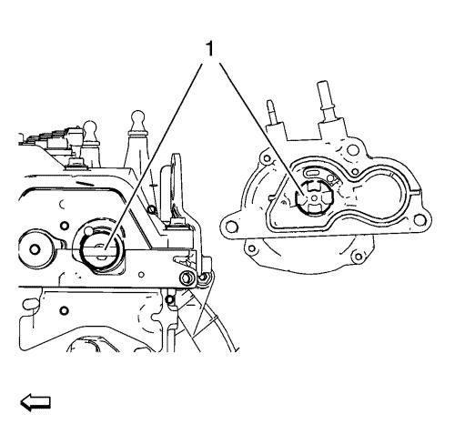
Note: The vacuum pump
gearing has to align with the camshaft notch (1).
|
| 1. |
Clean the sealing
surfaces. |
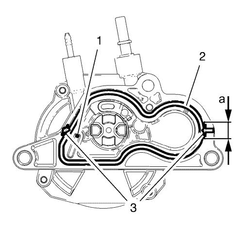
| 2. |
Install the seal ring (2) to
the vacuum pump, as shown in the graphic. |
|
Note: The sealing
compound should not close the oil hose (1) in the vacuum pump.
|
| 3. |
Apply sealing compound (3) for
a distance (a) of 8 mm (0.31 in) to the seal ring,
as shown in the graphic. |
|
Note: Mind the guide
sleeves
|
|
Note: Ensure the
proper seat of the seal ring (1).
|
| 4. |
Install the vacuum pump
(2). |
| 5. |
Install the 3 vacuum pump
bolts (3) and tighten to 24 N·m (18 lb ft)
. |
| 7. |
Install the negative pressure
hose (2). |
| 8. |
Install a NEW front intake
manifold gasket (1). |
| 9. |
Install the front intake
manifold (3). |
| 10. |
Install the 3 front intake
manifold bolts (2) and tighten to 16 N·m (12 lb
ft) . |
| 11. |
Install the 3 front intake
manifold bracket bolts (1, 2) and tighten to 24 N·m
(18 lb ft) . |
| 12. |
Connect the charger air cooler
outlet air hose (2) to the throttle body (1). |
| 16. |
Clip in the electronic control
module bracket. |
|
