Fuel Injection Pump Replacement
Special Tools
For equivalent regional tools, refer to
Special Tools .
Removal Procedure
| 5. |
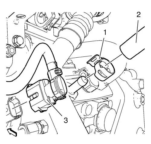
Remove the fuel feed pipe
clamp (1) and the fuel feed pipe (2). |
| 6. |
Disconnect the electrical
connection (3). |
|
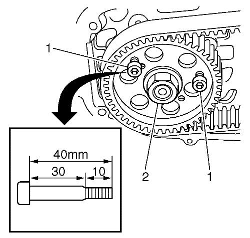
Note: When affixing
the pulley, use two hex socket head bolts M6 X 40 (30 mm unthread
and 10 mm thread). The bolt must be tightened the whole length of
the thread. This way the pulley is prevented from moving out of
position.
|
|
Note: Rotate the
engine only on crankshaft sprocket bolt and clockwise.
|
| 10. |
Fix the fuel injection pump
driven sprocket. |
| |
• |
Rotate the engine until it is
possible to install the 2 bolts (1). |
| |
• |
Install the 2 bolts
(1). |
| 11. |
Remove the fuel injection pump
driven sprocket nut (2) use EN-6347 holder in
conjunction with EN-956-1 extension to hold
up. |
| 12. |
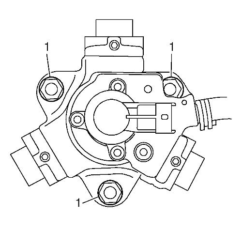
Remove the 3 fuel injection
pump nuts (1). |
| 13. |
Remove the fuel injection
pump. |
| |
• |
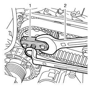
Pressing out the fuel
injection pump shaft from the pump driven sprocket, use
EN-46790 remover (1) and counter hold with a wrench
(2). |
| |
• |
Remove the fuel injection
pump. |
Installation Procedure
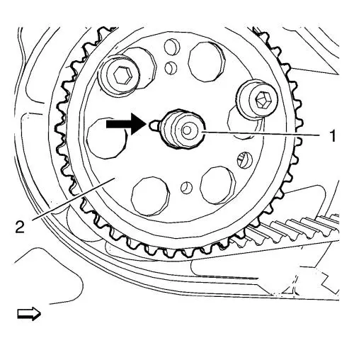
| 1. |
Position the fuel injection
pump shaft (1) in order that the key on it fits to the groove (see
arrow in picture) in the fuel injection pump driven sprocket
(2). |
| 2. |
Install the fuel injection
pump to the fuel injection pump bracket and the fuel injection pump
driven sprocket (2). |
| 3. |
Install the 3 nuts (1) and
tighten to 25 N·m (18 lb ft) . |
| 4. |
Install the fuel injection
pump driven sprocket nut (2) and tighten to 50 N·m
(37 lb ft) , use EN-6347 holder in
conjunction with EN-956-1 extension to hold
up. |
| 5. |
Remove the 2 bolts (1).
|
| 6. |
Connect the electrical
connection (3). |
| 7. |
Install the fuel feed pipe (2)
in conjunction with the fuel feed pipe clamp (1). |
| 14. |
To deflate the fuel system,
use the diagnostic tool to activate the low pressure pump for 60
seconds. |
|
