Intake Manifold Replacement (1.4L LDD)
Special Tools
| • |
EN-34730-91
Pressure Tester |
Removal Procedure
| 4. |
Remove engine sight
shield. |
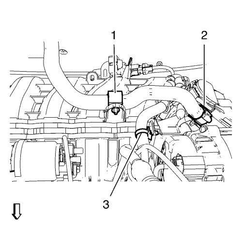
| 7. |
Unclip heater outlet hose from
retainer clip (1, 2). |
| 8. |
Unclip engine control module
wiring harness from retainer clip (3). |
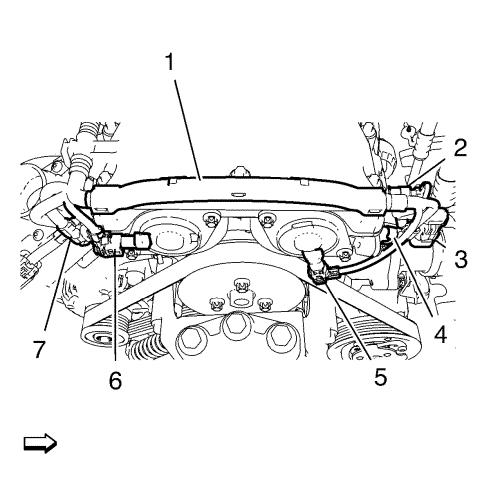
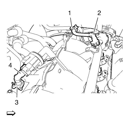
| 10. |
Remove engine control module
wiring harness (1) from camshaft cover: |
| |
• |
Disconnect intake camshaft
position sensor wiring harness plug (7). |
| |
• |
Disconnect intake camshaft
position actuator solenoid valve wiring harness plug (6).
|
| |
• |
Disconnect exhaust camshaft
position sensor wiring harness plug (4). |
| |
• |
Disconnect exhaust camshaft
position actuator solenoid valve wiring harness plug (5).
|
| |
• |
Disconnect engine coolant
temperature sensor wiring harness plug (3). |
| |
• |
Disconnect engine oil pressure
indicator switch wiring harness plug (2). |
| |
• |
Unclip engine control module
wiring harness (1) from camshaft cover. |
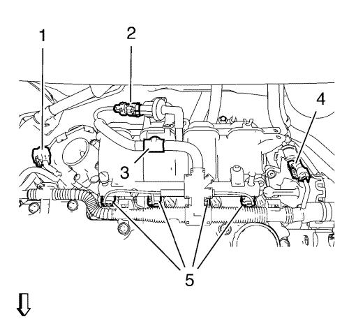
| 11. |
Disconnect engine control
module wiring harness from intake manifold upper: |
| |
• |
Disconnect throttle body
wiring harness plug (1). |
| |
• |
Disconnect evaporative
emission canister purge solenoid valve wiring harness plug
(2). |
| |
• |
Disconnect intake manifold
runner solenoid valve wiring harness plug (4). |
| |
• |
Unclip engine control module
wiring harness from intake manifold (3).. |
| |
• |
Disconnect the 4 fuel injector
wiring harness plugs (5). |
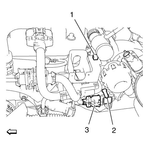
| 12. |
Disconnect the engine control
module wiring harness from retainer clip (1). |
| 13. |
Disconnect brake booster
vacuum pipe from intake manifold connector (2). |
| 14. |
Disconnect mass air flow
sensor wiring harness plug (3). |
| 15. |
Lay engine control module
wiring harness aside. |
| 16. |
Place collecting basin
underneath. |
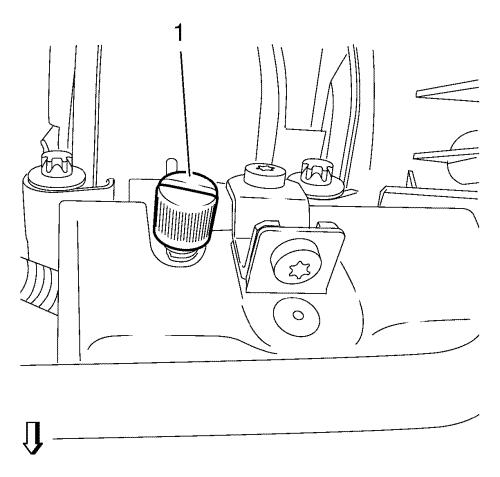
| 17. |
Remove fuel injector rail cap
(1). |
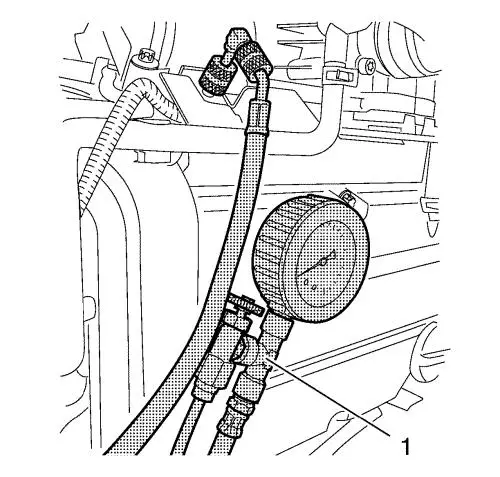
| 18. |
Relief fuel pressure. Use
EN-34730-91 pressure tester (1). |
| 19. |
Remove fuel feed pipe (2) from
fuel injector rail. |
| 20. |
Unclip fuel feed pipe from
retainer clip (1). |
| 21. |
Remove fuel ventilation pipe
(4) from evaporative emission canister purge solenoid valve.
|
| 22. |
Unclip fuel ventilation pipe
from retainer clip (3). |
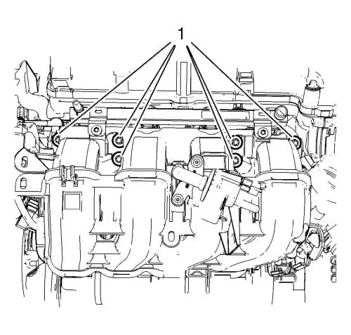
| 23. |
Remove the 6 intake manifold
bolts (1). |
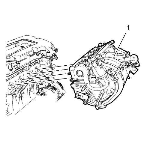
| 24. |
Remove the intake manifold (1)
in compound with the 5 seal rings. |
Installation Procedure
| 1. |
Clean sealing surfaces.
|
| 3. |
Install the intake manifold
(1) in compound with 5 NEW seal rings. |
| 4. |
Install the 6 intake manifold
bolts (1) and tighten to 20 N·m(15 lb ft)
. |
| 5. |
Clip fuel ventilation pipe to
retainer clip (3). |
| 6. |
Connect fuel ventilation pipe
(4) to evaporative emission canister purge solenoid valve.
|
| 7. |
Clip fuel feed pipe to
retainer clip (1). |
| 8. |
Connect fuel feed pipe (2) to
injector rail. |
| 9. |
Install fuel injector rail cap
(1). |
| 10. |
Connect the engine control
module wiring harness to retainer clip (1). |
| 11. |
Connect mass air flow sensor
wiring harness plug (3). |
| 12. |
Connect brake booster vacuum
pipe to intake manifold connector (2). |
| 13. |
Connect engine control module
wiring harness to intake manifold upper: |
| |
• |
Connect the 4 fuel injector
wiring harness plugs (5). |
| |
• |
Clip the engine control module
wiring harness to intake manifold (3). |
| |
• |
Connect intake manifold runner
solenoid valve (4). |
| |
• |
Connect the evaporative
emission canister purge solenoid valve wiring harness plug
(2). |
| |
• |
Connect the throttle body
wiring harness plug (1). |
| 14. |
Install engine control module
wiring harness to camshaft cover: |
| |
• |
Clip engine control module
wiring harness (1) to camshaft cover. |
| |
• |
Connect engine oil pressure
indicator switch wiring harness plug (2). |
| |
• |
Connect engine coolant
temperature sensor wiring harness plug (3). |
| |
• |
Connect exhaust camshaft
position actuator solenoid valve wiring harness plug (5).
|
| |
• |
Connect exhaust camshaft
position sensor wiring harness plug (4). |
| |
• |
Connect intake camshaft
position actuator solenoid valve wiring harness plug (6).
|
| |
• |
Connect intake camshaft
position sensor wiring harness plug (7). |
| 16. |
Clip engine control module
wiring harness to retainer clip (3). |
| 17. |
Clip heater outlet hose to 2
retainer clips (1) and (2). |
| 20. |
Install engine sight
shield. |
|
