Piston, Connecting Rod, and Bearing Replacement
Special Tools
EN-470-B Angular Torque Wrench
For equivalent regional tools, refer to
Special Tools .
Removal Procedure
|
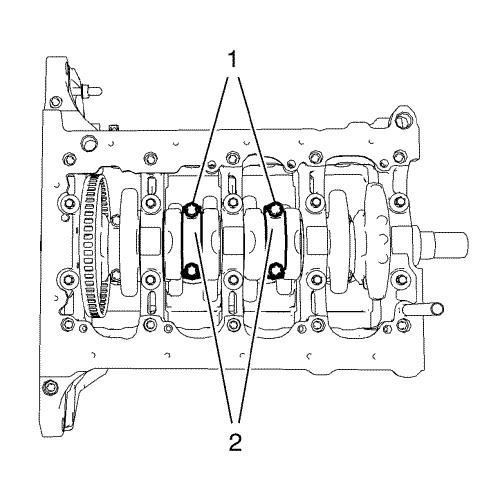
Note: Mark the
installation position of the connecting rod bearing caps. The
connecting rod bearings and bearing caps must not be interchanged
with other connecting rods.
|
| 5. |
Remove and DISCARD the 4
connecting rod bearing cap bolts (1) of cylinder 2 and 3.
|
| 6. |
Remove the 2 connecting rod
bearing caps (2) and the 2 connecting rod bearings of cylinder 2
and 3. |
| 7. |
Rotate the crankshaft
180° . |
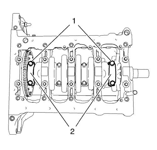
| 8. |
Remove and DISCARD the 4
connecting rod bearing cap bolts (1) of cylinder 1 and 4.
|
| 9. |
Remove the 2 connecting rod
bearing caps (2) and the 2 connecting rod bearings of cylinder 1
and 4. |
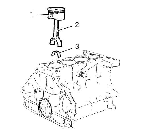
| 10. |
Remove the 4 pistons (1) and
connecting rods (2) and the 4 upper connecting rod bearings (3)
from the cylinder block. |
Installation Procedure
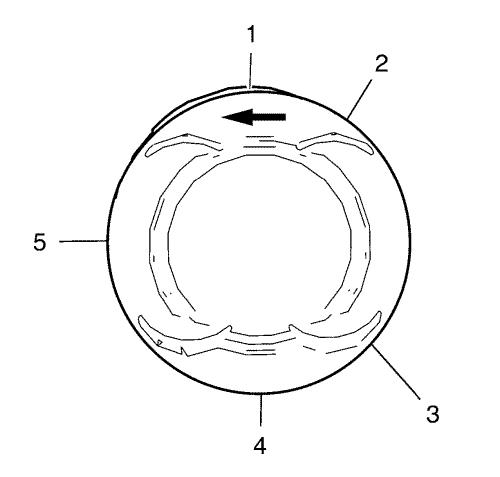
| 3. |
Adjust the piston ring joints
as followed: |
| |
3.1 |
Upper compression ring
(1) |
| |
3.2 |
Lower compression ring
(4) |
| 4. |
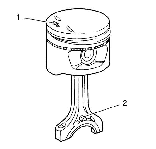
The arrow (1) on the piston
head must point to the timing side. |
| 5. |
The markings on the connecting
rods (2) must point to the transmission side. |
| 6. |
Lubricate the piston rings,
piston, inner cylinder bore surface and a piston ring compressor
with clean engine oil. |
| 7. |
Install the piston ring
compressor in order to compress the piston rings. |
| 8. |
Install the pistons (1) in
compound with connecting rods (2) and upper connecting rod bearings
(3) to the engine block and to the crankshaft. |
|
Note: The flarings
(arrows) on the connecting rod bearing caps must point to the
transmission side. The connecting rod bearing caps must be
installed in their original position.
|
| 9. |
Install the 2 connecting rod
bearings and the 2 connecting rod bearing caps (2) of cylinder 1
and 4. |
| 10. |
Install the 4 NEW connecting
rod bearing cap bolts (1) and tighten in the following
sequence: |
| |
10.1 |
Tighten the connecting rod
bearing cap bolts to 25 N·m (18 lb ft)
. |
| |
10.2 |
Tighten the connecting rod
bearing cap bolts an additional 25° . Use
EN-470-B wrench . |
| 11. |
Rotate the crankshaft
180° . |
|
Note: The flarings
(arrows) on the connecting rod bearing caps must point to the
transmission side. The connecting rod bearing caps must be
installed in their original position.
|
| 12. |
Install the 2 connecting rod
bearings and the 2 connecting rod bearing caps (2) of cylinder 3
and 2. |
| 13. |
Install the 4 NEW connecting
rod bearing cap bolts (1) and tighten in the following
sequence: |
| |
13.1 |
Tighten the connecting rod
bearing cap bolts to 25 N·m (18 lb ft)
. |
| |
13.2 |
Tighten the connecting rod
bearing cap bolts an additional 45° . Use
EN-470-B wrench . |
|
