Piston and Connecting Rod Assemble (1.4L LUH, LUJ and LUV)
Special Tools
EN-49941 Remover / Installer Piston Retainer Ring
For equivalent regional tools, refer to
Special Tools .
|
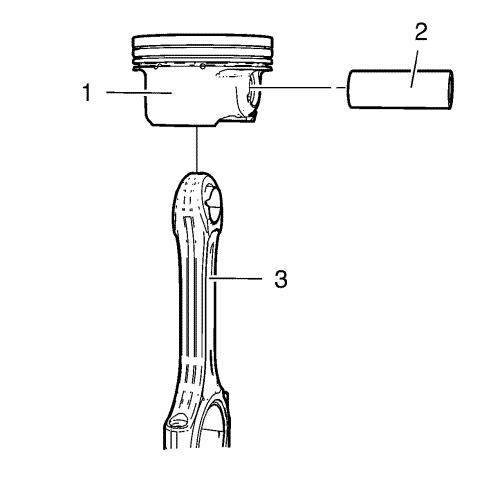
Note: Lubricate the
piston pin with clean engine oil.
|
| 1. |
Install the connecting rod (3)
and the piston pin (2) to the piston (1). |
| 2. |
Install the piston and
connecting rod assembly to a bench vise. Use aluminium
braces. |
|
Warning:
Use extreme care when removing snap rings. Always
wear adequate eye protection in order to avoid personal
injury. |
|
Warning:
Use care when removing or installing the piston
retainer ring. Ensure the EN-49941 remover/installer is installed
properly onto the retainer ring and that hands and fingers are kept
clear from the front of the tool. Otherwise, bodily injury may
occur. |
|
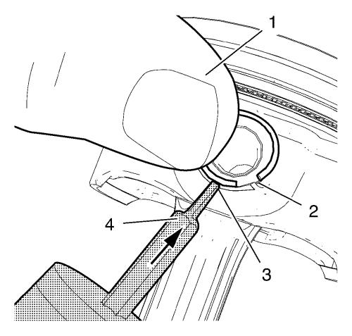
Note: Notch (2) on
right side.
|
| 3. |
Place the piston pin retainer
in the piston pin retainer groove so that the ring gap lays on the
notch (2). |
| 4. |
Push the piston pin retainer
down with the thumb in the shown position (1) and hold.
|
|
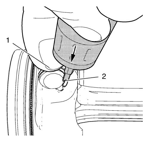
Note: The
EN-49941 installer should be applied in a
perpendicular position to the piston pin retainer.
|
| 5. |
Apply the EN-49941
installer (4) to the piston pin retainer in the position
shown (3) and push in direction of the arrow while pushing down
with the thumb. |
|
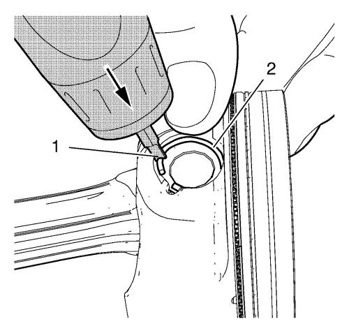
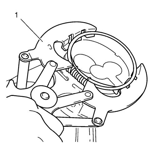
Note: Push the piston
pin retainer down in the position shown (2).
|
| 6. |
Move the EN-49941
installer (1) carefully to the position shown while pushing
in direction of the arrow until the piston pin retainer engages in
the piston pin retainer groove. |
| 7. |
Push down the piston ring
retainer to get a proper seat in the groove. |
|
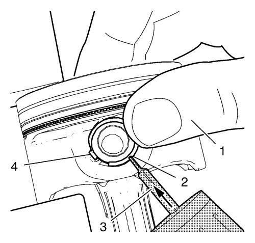
Note: Notch (4) on
left side. EN-49941 installer should be used with
left hand.
|
| 8. |
Place the piston pin retainer
in the piston pin retainer groove so that the ring gap lays on the
notch (4). |
| 9. |
Push the piston pin retainer
down with the thumb in the position shown (1) and hold.
|
|
Note: The
EN-49941 installer should be applied in a
perpendicular position to the piston pin retainer.
|
| 10. |
Apply the EN-49941
installer (3) to the piston pin retainer in the position
shown (2) and push in direction of the arrow while pushing down
with the thumb. |
|
Note: Push the piston
pin retainer down in the position shown (1).
|
| 11. |
Move the EN-49941
installer (2) carefully to the position shown while pushing
in direction of the arrow until the piston pin retainer engages in
the piston pin retainer groove. |
| 12. |
Push down the piston ring
retainer to get a proper seat in the groove. |
| 13. |
Remove the piston and
connecting rod assembly from the bench vise. |
| 14. |
Install the piston rings. Use
piston ring pliers (1). |
|
Note: Mind the TOP
marking on the piston rings.
|
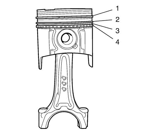
| 15. |
The piston rings must be
ordered as followed: |
| |
• |
Upper compression ring
(1) |
| |
• |
Lower compression ring
(2) |
| |
• |
Piston oil ring with spacer
(3), (4) |
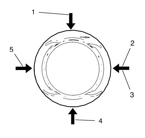
| 16. |
The piston ring joints must be
positioned 90° to each other. |
| |
• |
Upper compression ring joint
(2) |
| |
• |
Lower compression ring joint
(5) |
| |
• |
Oil ring joint, upper part
(1) |
| |
• |
Oil ring joint, lower part
(4) |
| |
• |
Oil ring spacer joint
(3) |
|
