Cylinder Head Disassemble
Special Tools
| • |
EN-6215
Mounting Equipment |
For equivalent regional tools, refer to
Special Tools .
|
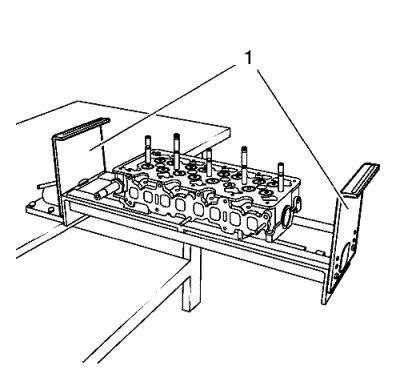
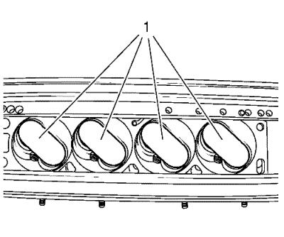
Note: Consider the
appropriate screwing on points for the EN-6215-5
side mounts .
|
| 1. |
Fit EN-6215-5
side mounts (1) for EN-6215-4 assembly device
. |
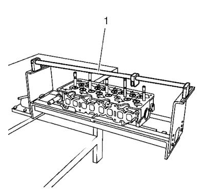
| 2. |
Install EN-6215-4
assembly device (1). |
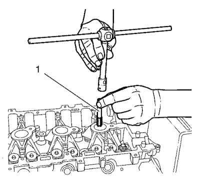
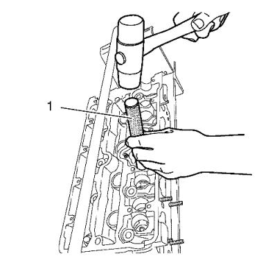
| 3. |
The spark plug threads must be
cleaned of combustion residues to ensure that the counterhold can
be attached correctly. Insert tap M14 x 1.25 (1) in the spark plug
thread and screw in evenly. |
| 4. |
Turn the cylinder head
baseplate. |
|
Note: There are 2
kinds of counter holder. Type A and Type B. Choose the correct type
for the existing combustion chamber.
|
| 5. |
Install the counter
holder. |
|
Note: Depending upon
the combustion chamber organization, it must be used different
holders to protect the valves.
|
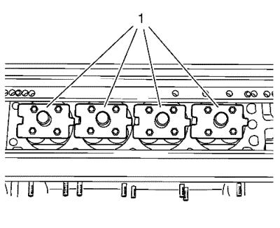
| 6. |
Counter holder type A
(1). |
|
Note: Depending upon
the combustion chamber organization, it must be used different
holders to protect the valves.
|
| 7. |
Counter holder type B
(1). |
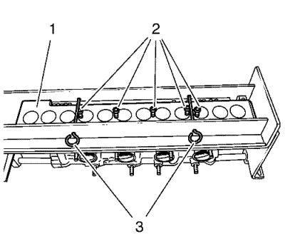
| 8. |
Install the EN-6167
fixing tool (1). Attach the EN-6215-3
mounting equipment (3) with safety lock pins. Install the fixing
bolts (2). Turn the cylinder head baseplate again. |
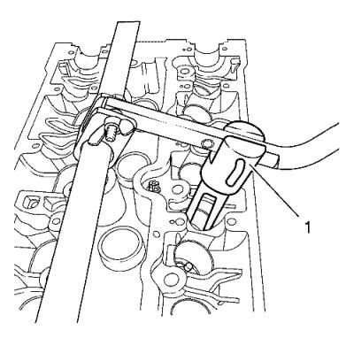
| 9. |
To ensure that no special
tools are damaged during the disassembly of the valve wedges, the
valve retainers are to release with EN-6171 release
tool (1). Put the EN-6171 release tool on the valve
retainers and with a short impact of a rubber hammer all valve
retainers will loose (setting behaviour). |
|
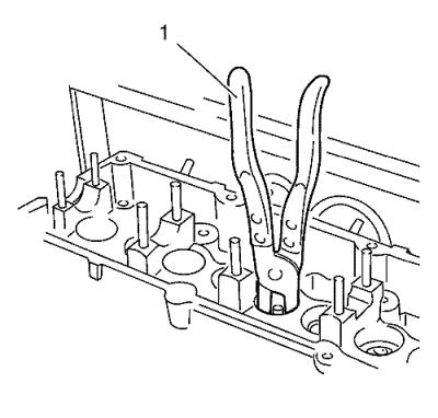
Note: The
valve-spring depressing tool (1) must be positioned parallel onto
the valve spring cap to ensure that neither tools nor components
are damaged. Select the appropriate bore in the lever for this
purpose. If the valve-spring compressor cannot be positioned
parallel, the lever must be adjusted accordingly.
|
| 10. |
Push the depressing tool (1)
down with lever until the valve spring cap is released. Remove
valve cotters. |
| 11. |
Remove the upper valve spring
cap and valve springs and place them in sequence on EN-849
assembly tray . |
| |
Release the valve stem sealings by turning with EN-840
remover (1) and remove from the valve guides. |
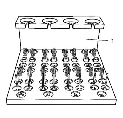
| 12. |
Remove lower valve spring caps
or valve rotators from cylinder head and also place on
EN-849 valve box (1). |
| 14. |
Turn cylinder head baseplate.
Remove wooden board EN-6215 mounting equipment and
counter holder if attached. |
| 15. |
Remove all valves in sequence
and place on EN-849 assembly tray (1) in
sequence. |
|
