Piston, Connecting Rod, and Bearing Replacement
Special Tools
| • |
EN-45059
Torque Angle Sensor |
| • |
CH-49290
Mounting Engine / Transmission |
For equivalent regional tools, refer to
Special Tools .
Removal Procedure
| 5. |
Remove the CH-49290
mounting , for disassembly use attached installation
manual. |
| 7. |
Set crankshaft to TDC of
combustion stroke of cylinder 1. |
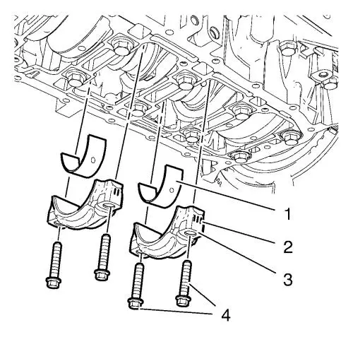
| 8. |
Remove and DISCARD the 4
connecting rod bearing cap bolts (4) from the cylinder 2 and
3. |
|
Note: Note the
marking (2) of the connecting rod bearing caps.
|
|
Note: The shear
surfaces of the connecting rod and the connecting rod bearing cap
form a unique fit and must not be swapped or damaged. Do not lay
down on the shear surfaces.
|
| 9. |
Remove the 2 connecting rod
bearing caps (3) from the cylinder 2 and 3. |
| 10. |
Remove the 2 connecting rod
lower bearings (1). |
|
Note: Set aside in
the order removed.
|
|
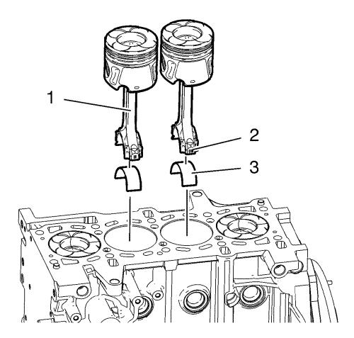
Note: Take extreme
care to prevent damage to the cylinder bore surface, piston ring
and piston surface.
|
| 12. |
Push the 2 pistons with
connecting rod (1) from the cylinder 2 and 3 upwards. |
|
Note: Note the
marking (2) of the connecting rod. Set aside in the order
removed.
|
| 13. |
Remove the 2 connecting rod
upper bearings (3) from the cylinder 2 and 3. |
| 14. |
Turn the crankshaft through
180° and set the crankshaft to TDC of
combustion stroke of cylinder 2. |
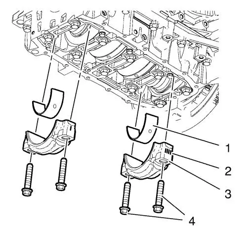
| 16. |
Remove and DISCARD the 4
connecting rod bearing cap bolts (4) from the cylinder 1 and
4. |
|
Note: Note the
marking (2) of the connecting rod bearing caps. Set aside in the
order removed.
|
|
Note: The shear
surfaces of the connecting rod and the connecting rod bearing cap
form a unique fit and must not be swapped or damaged. Do not lay
down on the shear surfaces.
|
| 17. |
Remove the 2 connecting rod
bearing caps (3) from the cylinder 1 and 4. |
|
Note: Set aside in
the order removed.
|
| 18. |
Remove the 2 connecting rod
lower bearings (1). |
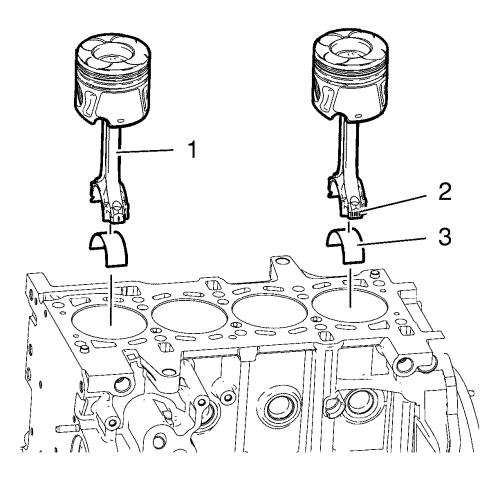
|
Note: Take extreme
care to prevent damage to the cylinder bore surface, piston ring
and piston surface.
|
| 19. |
Push the 2 pistons with
connecting rod (1) from the cylinder 1 and 4 upwards. |
|
Note: Note the
marking (2) of the connecting rod. Set aside in the order
removed.
|
| 20. |
Remove the 2 connecting rod
upper bearings (3) from the cylinder 1 and 4. |
Installation Procedure
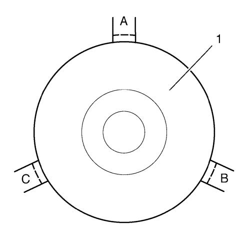
| 2. |
Turn the piston rings before
the installation to a position (A, B C) as in the graphic
shown. |
|
Note: Arrow on piston
head points to engine timing side.
|
| 3. |
Lubricate the piston rings,
piston, inner cylinder bore surface and a piston ring with clean
engine oil. |
| 4. |
Install the piston ring
compressor in order to compress the piston rings. |
|
Note: Take extreme
care to prevent damage to the cylinder bore surface, piston ring
and piston surface.
|
| 5. |
Install the 2 connecting rod
upper bearings (3) to the connecting rod of the cylinder 2 and
3. |
| |
Push the 2 pistons with connecting rod (1) to the cylinder 1
and 4. |
|
Note: Take extreme
care to prevent any scratches or damages to the connecting rod
bearings.
|
| 7. |
Install the 2 connecting lower
bearings (1). |
| 8. |
Install the 2 connecting rod
bearing caps (3) to the cylinder 1 and 4. |
| 9. |
Install the 4 NEW connecting
rod bearing cap bolts (4) to the cylinder 1 and 4 and tighten in
two passes: |
| |
• |
First pass to 25
N·m (18 lb ft) . |
| |
• |
Second pass to
60° , using the EN-45059
sensor . |
| 10. |
Turn the crankshaft through
180° and set crankshaft to TDC of combustion
stroke of cylinder 2. |
|
Note: Take extreme
care to prevent damage to the cylinder bore surface, piston ring
and piston surface.
|
| 12. |
Install the 2 connecting rod
upper bearings (3) to the connecting rod of the cylinder 2 and
3. |
| 13. |
Push the 2 pistons with
connecting rod (1) to the cylinder 2 and 3. |
|
Note: Take extreme
care to prevent any scratches or damages to the connecting rod
bearings.
|
| 15. |
Install the 2 connecting rod
lower bearings (1). |
| 16. |
Install the 2 connecting rod
bearing caps (3) to the cylinder 2 and 3. |
| 17. |
Install the 4 NEW connecting
rod bearing cap bolts (4) to the cylinder 2 and 3 and tighten in
two passes: |
| |
• |
First pass to 25
N·m (18 lb ft) . |
| |
• |
Second pass to
60° , using the EN-45059
sensor . |
| 18. |
Set the crankshaft in
direction of the engine rotation to 60° before
TDC of combustion stroke of cylinder 1. |
| 20. |
Install the CH-49290
mounting , for assembly use attached installation
manual. |
|
