Transmission Replacement (2.0L Diesel LBS and LBX)
Special Tools
| • |
CH-49290
Engine Support Tool |
| • |
DT-47648
Transmission Holder |
| • |
EN-47649
Engine Support Fixture |
For equivalent regional tools, refer to
Special Tools .
Removal Procedure
| 5. |
Drain the transmission
fluid. |
| 7. |
Disconnect the electrical
connector transmission control module (TCM). |
| 8. |
Remove the transmission vent
hose. |
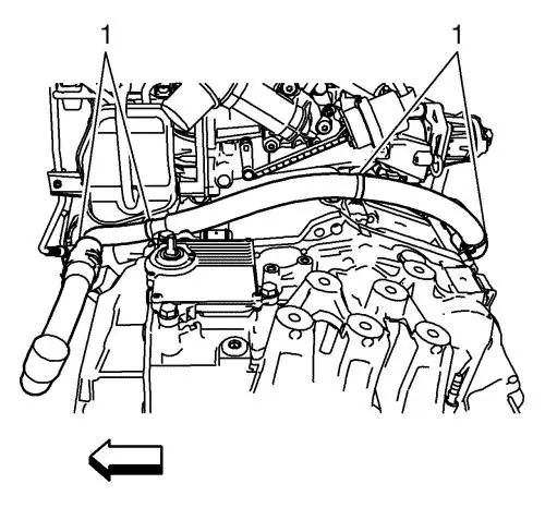
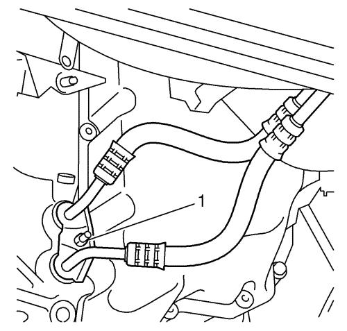
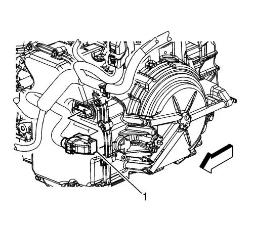
| 9. |
Remove the wiring harness
starter motor from transmission. Remove 4 clips (1). |
| 10. |
Remove the upper middle wiring
harness starter motor bracket. Remove the nut. |
| 11. |
Remove the 2 upper
transmission bolts (2). |
|
Note: The SPX
installation manual is supplied with the special tool and is also
available online from SPX directly. Go to
www.spxtools-shop.com.
|
| 14. |
Assemble the CH-49290
support tool (1) according to the details provided in the
SPX installation manual. |
| 15. |
Support the CH-904
base frame on a jack. |
| 16. |
Support the CH-49290
support tool on the CH-904 base frame
. |
|
Note: The SPX
installation manual is supplied with the special tool and is also
available online from SPX directly. Go to
www.spxtools-shop.com.
|
| 17. |
Install the CH-49290
support tool (1) according to the details provided in the
SPX installation manual. |
| 20. |
Mark the relationship of the
flex plate to the torque converter for reassembly. |
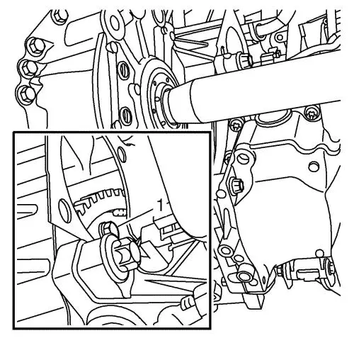
| 21. |
Remove and DISCARD the torque
converter to flywheel bolts (1). |
| 27. |
Remove the fluid cooler hose
from the transmission. Remove nut (1). |
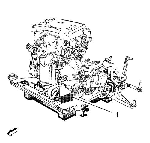
| 31. |
Lower the engine and the
transmission on the left hand side with the EN-47649
engine support fixture to allow clearance for
removal. |
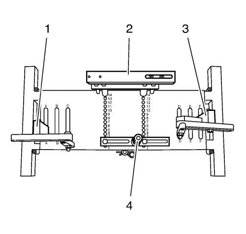
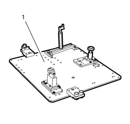
| 33. |
Place DT-47648
transmission holder on CH-904 base frame and
pre-install the supports as shown in the illustration. |
| 34. |
Pre-install
DT-47648-2 converter housing support (4) to
position 1 on the base plate. |
| 35. |
Pre-install
DT-47648-4 transmission housing support (2) to
position 14 on the base plate. |
| 36. |
Pre-install DT-47648-5
left support with rear transmission swivel arm (1) to
position A on the base plate. |
| 37. |
Pre-install DT-47648-5
right support with front transmission swivel arm (3) to
position F on the base plate. |
|
Note: Before placing
in position slacken all bolt connections of the swivel arms and
supports as far as the base plate. Adjust the supports for the
converter housing and transmission housing using the spindles until
they are as low as possible.
|
| 38. |
Attach the DT-47648
transmission holder to the transmission. |
| 39. |
Align DT-47648
transmission holder under transmission. |
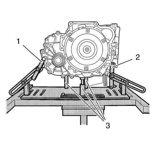
| 40. |
Attach swivel arms (1, 2) to
transmission. |
|
Note: Align the
swivel arms so that as little leverage as possible is created.
|
| 41. |
Tighten the bolt connections
of the swivel arms, starting from the transmission and going as far
as the base plate. |
| 42. |
Position supports for
converter housing and transmission housing on transmission by twist
up the spindles (3). |
| 43. |
Tighten bolt connections of
the supports. |
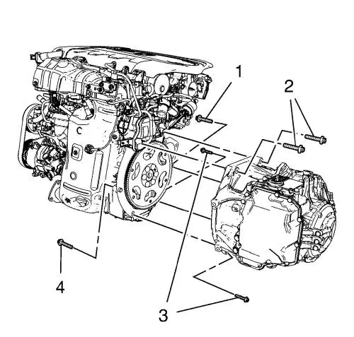
| 44. |
Remove the transmission bolts
(1, 3, 4). |
|
Note: Insure the
torque converter remains securely in place on the transmission
input shaft while separating and removing the transmission.
|
| 45. |
Separate the transmission from
the engine. |
| 46. |
Lower the transmission with
the transmission jack and DT-47648 transmission
holder far enough to remove the transmission. |
Installation Procedure
| 1. |
If the removed transmission
will be reinstalled, re-cut the 6 threads of torque
converter. |
| 2. |
Raise the transmission with
the transmission jack and DT-47648 transmission
holder and position the transmission to the engine. |
| 3. |
Install the transmission bolts
(1, 4) and tighten to 60 N·m (44 lb ft)
. |
| 4. |
Install the transmission bolt
(3) and tighten to 40 N·m (30 lb ft)
. |
| 5. |
Remove the transmission jack
with the DT-47648 transmission holder .
|
| 7. |
Raise the engine and the
transmission on the left hand side with the EN-47649
engine support fixture . |
| 8. |
Install the 3 NEW transmission
mount bolts but do not tighten yet. |
|
Note: Service may
offer bolts that are not microencapsulated. If this is the case
apply thread lock agent to the bolts.
If fasteners are microencapsulated, install NEW torque
converter to flywheel bolts. DO NOT reuse the old bolts.
|
| 10. |
Install the NEW torque
converter to flex plate bolts (1) and tighten to 60
N·m (44 lb ft) . |
| 19. |
Install the upper transmission
to engine bolts (2) and tighten to 60 N·m (44 lb
ft) . |
| 20. |
Tighten the 3 NEW left
transmission mount bolts a first pass to 50 N·m (37
lb ft) . |
| 21. |
Tighten the 3 NEW left
transmission mount bolts a final pass to an additional 60
to 75 degrees , using the EN-45059 meter
. |
| 23. |
Lower the CH-49290
support tool (1) with the CH-904 base frame
and a jack. |
| 24. |
Remove the CH-49290
support tool from the CH-904 base frame
. |
|
Note: The SPX
installation manual is supplied with the special tool and is also
available online from SPX directly. Go to
www.spxtools-shop.com.
|
| 25. |
Disassemble the
CH-49290 support tool (1) according to the details
provided in the SPX installation manual. |
| 26. |
Install the fluid cooler hose
to transmission. Install nut (1) and tighten to 9
N·m (80 lb in) . |
| 30. |
Connect the electrical
connector transmission control module (TCM). |
| 31. |
Install wiring harness starter
motor to transmission. Install 4 clips (1). |
| 32. |
Install upper middle wiring
harness starter motor bracket. Install nut. |
| 33. |
Install transmission vent
hose. |
| 36. |
Fill the transmission with
correct fluid. |
| 40. |
Carry out adaptation,
resetting and program the gear selector position sensor in "N"
neutral position, using the scan tool. Refer to
Transmission Adaptive Functions . |
|
