Assemblies, Install in Transmission
 Clean Clean All sealing surfaces of transmission housing, converter housing and rear cover.
 Assemble Assemble Insert intermediate gear (1) in transmission housing and carefully drive in to stop with plastic hammer: turn transmission 90 ° in mount and lock. Insert retaining ring for intermediate gear (driving) with KM-396 (2). Coat piston seal rings with transmission fluid and attach to piston (5) for multi-disc brake B2:
|
3 |
Piston seal ring (outer) |
|
4 |
Piston seal ring (inner) |
| 
|
 Install, Connect Install, Connect Piston (1) for multi-disc brake B2 - do not damage seal rings. Return springs assembly (2) on piston B2. Insert retaining ring (3) in dedicated groove with suitable screwdriver. Ensure that the retaining ring sits correctly in groove. Insert flanges (4), lining plates (5) and steel plates (6) - number of steel and lining plates see "Technical Data". Insert retaining ring (7) for multi-disc brake B2 with screwdriver. | 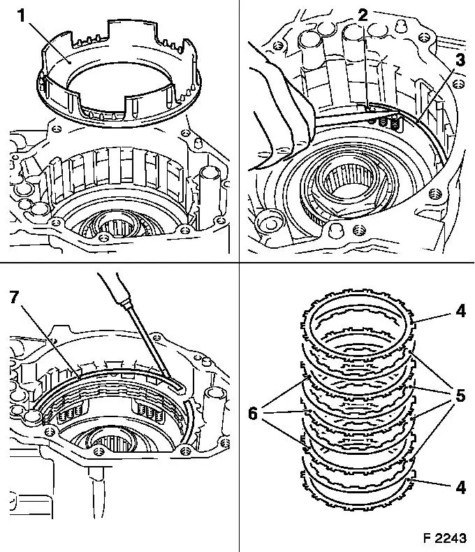
|
 Inspect Inspect Lift piston B2 and thus check function - blow low pressure compressed air into bore for B2 (arrow).
Install, Connect Align lining plates of multi-disc brake B2. Insert front ring gear with overrunning clutch F1 (2) in multi-disc brake B2 - install axial needle bearing (3). Cement thrust washer (1) to planetary carrier with assembly grease. Install planetary carrier (5) and sun gear (4). Clutch hub for multi-plate clutch CO (6). Insert retaining ring with retaining ring pliers (7). | 
|
Install, Connect Place axial needle bearing (4) and thrust washer (3) on planetary carrier or sun gear. Stick axial needle bearing (1) and thrust washer (2) to rear ring gear with overrunning clutch F0 using assembly grease. Rear ring gear with overrunning clutch F0 (7) on planetary carrier - mesh ring gear with planetary gears. Axial needle bearing (6) and thrust washer (5). Align lining plates of C0 and C3. Multi-plate clutch assembly C0 and C3 (8).
 Measure Measure Dimension "9" should be 41 to 43 mm. | 
|
Install, Connect Attach thrust washer (2) to multi-plate clutch assembly C1 with assembly grease - thereby ensure that slotted seal rings (3) and thrust washer (1) are mounted. Align lining plates of C1. Install multi-plate clutch assembly C1 (4). Gaskets (5 and 6) in transmission housing. Attach axial needle bearing assembly with thrust washer (7) and 4 cut seal rings (8) to spigot of rear housing cover with assembly grease. Rear housing cover with sealing compound to transmission housing (arrows).
 Tighten (Torque) Tighten (Torque) Rear housing cover to transmission housing - 25 Nm / 18.5 lbf. ft. | 
|
Lock transmission horizontally.
Install, Connect Place axial needle bearing (1) on roller bearing. Carefully insert pipe (3), if necessary with plastic hammer. Fastening clamp for pipe, 1 bolt (2) - 6 Nm / 4 lbf. ft. Thrust washers (4 and 5) to intermediate gear (driven). Insert intermediate gear, driven (6). Fluid strainer (7). Fluid carrier plate - 2 bolts (8) - 6 Nm / 3.5 lbf. ft. Drive in new seal ring for transmission selector lever shaft flush with suitable socket wrench (9). Note installation position of seal ring. | 
|
Install, Connect Install transmission selector lever shaft (1) with toothed segment (3) and "new tension sleeve" in transmission housing. Drive in new tensioning pin with suitable drift (2). Then turn sleeve slightly (arrow) and caulk at groove in shaft. Insert actuating rod for parking paw l (4) in toothed segment. Pin for parking pawl (7). Parking pawl claw (6), pin (5) with torsion spring No. 1. Guide for parking pawl claw (10) - bolt "8" and bolts "11" with sleeve and torsion spring No. 2 (9).
Tighten (Torque) Guide for parking pawl claw to transmission - 10 Nm / 7 lbf. ft. | 
|
Tighten (Torque) Lock spring - 2 bolts (3) to transmission - 10 Nm / 7 lbf. ft.
Install, Connect Anchor pin (1) for brake band B1. Brake band B1 (2) - ensure that the recess in the brake band faces the piston rod. Stick axial needle bearing with thrust washer (4) and thrust washer (6) to multi-plate clutch assembly C2 (5) with assembly grease. Multi-plate clutch assembly C2 (7). Thrust washer (9) and slotted seal rings (8) to fluid pump with assembly grease. | 
|
Install, Connect Turn fluid pump 180 ° . Coat new O-ring (1) with transmission fluid and to fluid pump. Fluid pump (3) in transmission housing - insert bolts (x 6) and tighten fluid pump uniformly.
Tighten (Torque) Fluid pump to transmission - 25 Nm / 18.5 lbf. ft.
Install, Connect Differential (2) in transmission housing. Gaskets (x 3, arrows). Illus. F2250 shows differential with speedometer gear (driving). | 
|
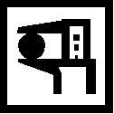
Install, Connect Piston for brake band B1: Insert piston (1) for brake band B1 with spring (2) and new O-rings (3) - coat O-rings with transmission fluid, do not damage. Attach retaining ring for piston brake band B1 (6) with retaining ring pliers. Insert cover (4) with new O-ring (5). Attach retaining ring for piston brake band B1 (7) with retaining ring pliers. | 
|
Inspect Check function of piston (1) for brake band B1 - blow low pressure compressed air into bore for B1 (arrow) in transmission housing. | 
|
Install, Connect Coat sealing surfaces of transmission housing and converter housing with sealing compound. Place converter housing on transmission housing and screw in bolts (x 15, arrows).
Tighten (Torque) Converter housing to transmission housing - 25 Nm / 18.5 lbf. ft. | 
|
Inspect If not yet installed, lever out old axle shaft seal rings with screwdriver.
Install, Connect Drive in new axle shaft seal rings to stop with KM-446 (1) with plastic hammer. | 
|
If still removed, shift valve (1) with control lever (2) in valve body. Transmission wiring harness with new O-ring to transmission housing - 1 bolt (3). | 
|
Install, Connect Attach new gaskets (1) to transmission with assembly grease. Install valve body - do not thereby trap solenoid valves wiring harness and insert control lever (2) in toothed segment. Install bolts (x 6, arrows). Install intake cover (3) with new gasket - 2 bolts. Install bracket - 1 bolt (4). Solenoid valves (if not yet installed) and wiring harness plug.
|
5 |
Pressure regulator |
|
6 |
2-3 shift |
|
7 |
1-2 / 3-4 shift |
|
8 |
Converter clutch |
|
9 |
Temperature sensor |
6 bolts (arrows), 1 bolt (4), 2 bolts for intake cover, tightening torque - 10 Nm / 7 lbf. ft. | 
|
Install, Connect Attach side cover to transmission with sealing compound and insert bolts (x 13, arrows).
Tighten (Torque) Side cover to transmission - 25 Nm / 18.5 lbf. ft. Transmission input speed sensor (1) - black - and transmission output speed sensor (2) - grey - to transmission - 5 Nm / 3.5 lbf. ft. Connect wiring harness plug. Selector lever position switch to transmission - 2 bolts (3) - do not tighten yet. Nut (5) with retaining plate (4) to shaft - 7 Nm / 5 lbf. ft. Secure retaining washer (6) with screwdriver. | 
|
 Adjust Adjust Selector lever position switch - see operation "Selection Lever Position Switch, Adjust (up to MY '96)" or "Selection Lever Position Switch, Adjust (as of MY '96)"
Tighten (Torque) Fluid drain screw (1) with new gasket to transmission - 40 Nm / 29.5 lbf. ft. Insert converter with KM-899 (arrows) in converter housing. | 
|
 Remove, Disconnect Remove, Disconnect Transmission with Transmission Mount KM-910 (2) from KM-113-2 (1). KM-910 from transmission.
 Important! Important! Before the engine is started after re-installing the transmission, the transmission must be charged with transmission fluid Dexron ® II (filling quantity approx. 5 litres). | 
|
|
