End Shield, Assemble (F 15) End shield components
4 3rd/4th gear shift fork
6 1st/2nd gear shift fork
 Install, Connect Install, Connect | 
|
Press reverse idler gear axle with inserted lock ball (arrow) to stop in end shield.
 Important! Important! Note installation position. | 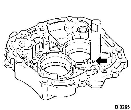
|
Install, Connect Heat bearing seats for main shafts and gear clusters to approx. 80 ° C/176 ° F. Insert main shaft, gear cluster and reverse idler gear in end shield and secure with KM-444-3 (see illus. I). Retaining rings must engage properly in grooves. Lubricate bearing and return bore. Groove on reverse idler gear shift fork points up.
Install, Connect Insert reverse, 1st/2nd gear lock pin (see illus. III). Insert shift fork and shift rod and pin with KM-308-2 (see illus. II). Allow new coiled pin to protrude approx. 2 mm/0.08 in. Install shift rod reverse gear pawl (see illus. III). Insert 1st/2nd gear shift fork and shift rod and pin in place (see illus. III).
Important! To prevent stress on rod guides in end shield, support shift rods with wooden wedge when pinning. | 
|
Install, Connect Install 1st/2nd gear shift rod pawl, drive in to stop with plastic hammer or soft metal drift. Insert 5th gear shift driver. Insert 3rd/4th gear shift fork and shift rod and pin (see illus. I).
Important! To prevent stress on shift rod guide, support shift rods with wooden wedge.
Install, Connect Install 5th gear and 3rd/4th gear shift rod pawl, drive in to stop with plastic hammer or soft metal drift. Put shift forks into neutral (see illus. I). 2./3./5. Engage 2nd/3rd/5th gear. Fasten bridge for lock pin on end shield (see illus. II) - 7 Nm / 5 lbf. ft. Coat new bolts (not micro-encapsulated) with locking compound. Put gearshift lever in neutral. | 
|
Install, Connect Fasten bearing support on end shield with pawl (arrow) - 7 Nm / 5 lbf. ft. Insert new fastening bolts with locking compound. | 
|
Heat 5th gear (large) to approx. 100 ° C/212 ° F. Push on gear with KM-466-3.
Important! Long gear hub points to end shield.
Install, Connect Install new retaining ring. | 
|
Install, Connect Lubricate both 5th gear needle bearings with transmission fluid and install on main shaft, ensure that split needle bearings are correctly seated (see illus. I). Lubricate seating surface of main shaft and synchroniser hub with transmission fluid. Push 5th gear (small) and synchroniser hub with slider sleeve onto main shaft (see illus. II). Select new retaining ring and install. Compensation for shaft end play (gear cluster) (see illus. III). | 
|
Install, Connect Insert sliding shoes in 5th gear shift fork. Mount bearing support with cam follower on end shield - 22 Nm / 16 lbf. ft. Insert new bolts with locking compound.
Important! Ensure that play is not greater than approx. 0.2 mm/0.008 in.
Install, Connect | 
|
Install thrust washer on reverse idler axle. Stick thrust washer with bearing grease. | 
|
Install, Connect Stick on end shield gasket with a little bearing grease. Guide end shield into transmission housing and fasten to transmission housing. Stick on cover gasket with a little bearing grease. Attach transmission cover and install two fit bolts (arrow, see illus. I) first. Install transmission cover with 4 long bolts, fit bolts and stud for ground strap.
 Tighten (Torque) Tighten (Torque)
|
End shield to transmission housing |
- 22 Nm / 16 lbf. ft. |
|
End shield to transmission (M7 x 1) |
- 15 Nm / 11 lbf. ft. |
|
End shield to transmission (M8 x 1.25) |
- 20 Nm / 15 lbf. ft. |
|
|
|
 Adjust Adjust Adjust 5th gear shift fork stop pin. Set play to 0.2 mm/0.008 in. with feeler gauge (see illus. II). | 
|
Install, Connect Install reversing lamps switch and speedometer drive (driven). Stick shift cover gasket to transmission housing and install cover.
Tighten (Torque)
|
Reversing lamps switch to transmission |
- 20 Nm / 15 lbf. ft. |
|
Speedometer drive to housing |
- 4 Nm / 3 lbf. ft. |
|
Shift cover to transmission housing |
- 12 Nm / 9 lbf. ft. |
|
|
|
Install, Connect | 
|
Install clutch thrust bearing fork and release lever. Coat sliding surface on guide sleeve with special grease. | 
|
|
