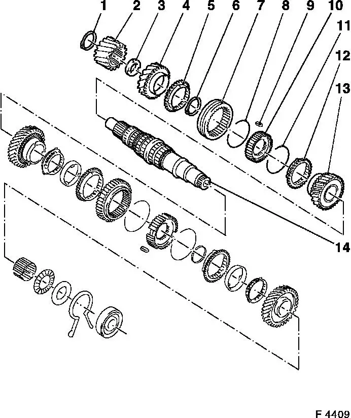
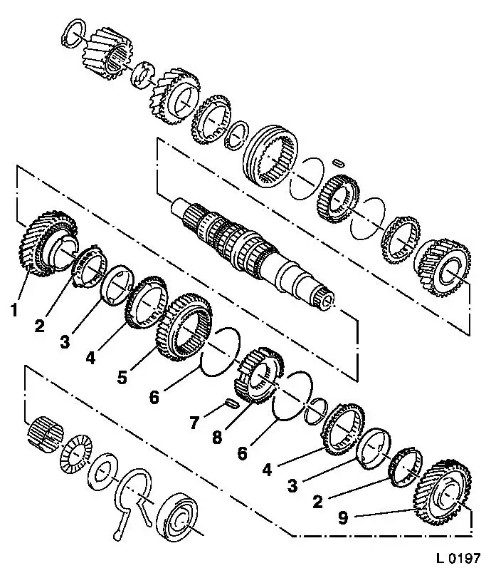
Main Shaft, Disassemble and Assemble (F 13) Illustration Notice: Provision of the main shaft with needle bearings for the gears may deviate from the example shown here.
5 4th gear synchroniser ring
7 3rd/4th gear shift sleeve
12 3rd gear synchroniser ring
| 
|
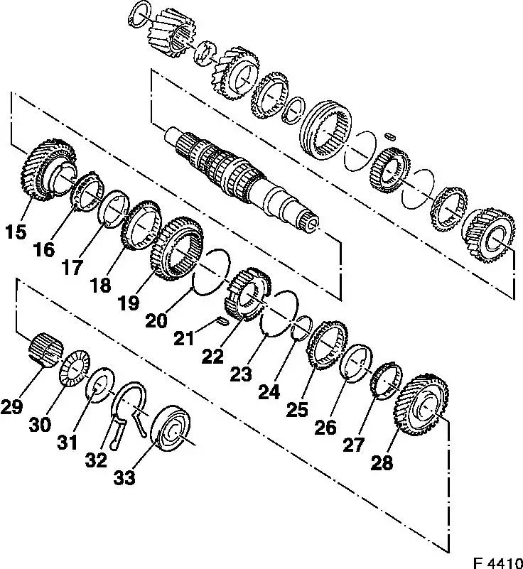
Illustration (Continued)
|
15 |
2nd speed gear |
|
16 |
Inner synchroniser ring |
|
17 |
Intermediate ring |
|
18 |
Outer synchroniser ring |
|
19 |
1st/2nd gear shift sleeve |
|
20 |
Synchroniser spring |
|
21 |
Sliding block |
|
22 |
Synchromesh body |
|
23 |
Synchroniser spring |
|
24 |
Retaining ring |
|
25 |
Outer synchroniser ring |
|
26 |
Intermediate ring |
|
27 |
Inner synchroniser ring |
|
28 |
1st speed gear |
|
29 |
1st gear needle bearing |
|
30 |
Axial needle bearing |
|
31 |
Thrust washer |
|
32 |
Retaining ring |
|
33 |
Ball bearing |
| 
|
Notice: Transmission remains installed.
 Remove, Disconnect Remove, Disconnect Remove cover (1) for shift mechanism - see operation "Cover for Shift Mechanism, Remove and Install and / or Seal". Remove reversing lamps switch (2). Remove gasket for end shield cover (3) - see operation "Gasket for End Shield Cover, Replace". Remove end shield (4) from transmission - see operation "Gasket for End Shield, Replace". | 
|
Remove, Disconnect Remove main shaft - see operation "End Shield, Disassemble and Assemble (F 13)". Notice: If the gears are damaged, always also replace the gear cluster.
 Disassemble Disassemble Press off ball bearing (3), spacer washer (4), retaining ring (6), output shaft (5) and gearwheel for 1st gear (7) with suitable drift (1) in conjunction with KM-307-B (2). Remove needle bearing (8) for 1st gear from main shaft. Remove inner synchroniser ring (9), intermediate ring (10) and outer synchroniser ring (11) for 1st gear from synchromesh body assembly (12). | 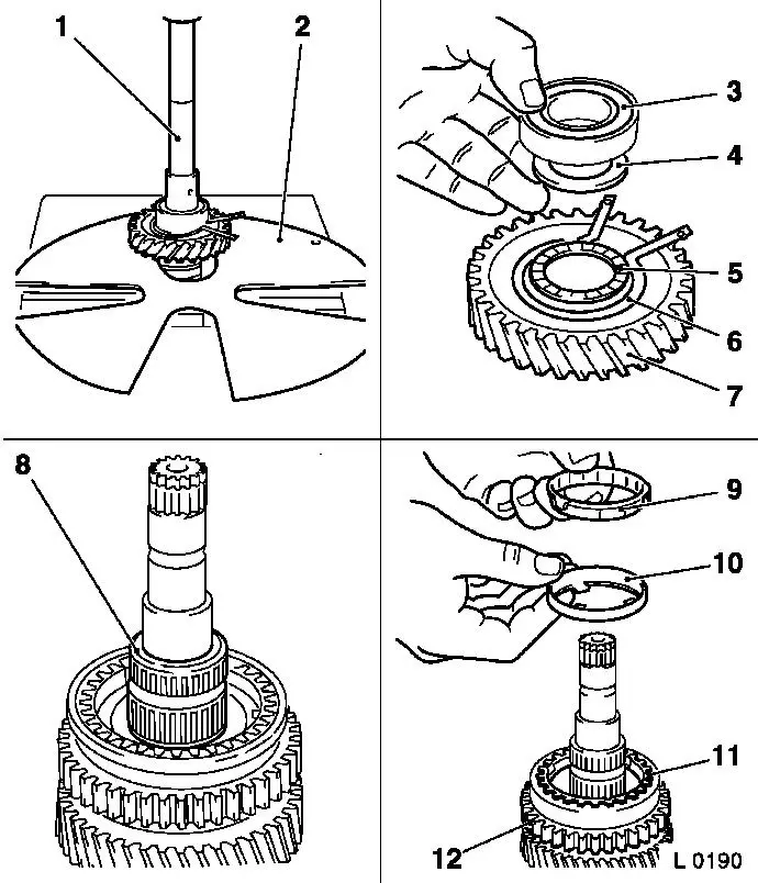
|
Disassemble Remove retaining ring for 1st/2nd gear synchromesh body assembly (1) with ring pliers (2). Remove shifter collar (7), synchroniser spring (6) and slide blocks (3 and 5) from synchromesh body (4). Press off synchromesh body (8), inner synchroniser ring (9), intermediate ring (10) and outer synchroniser ring (11) for 2nd gear, and for 2nd gear (12) with suitable drift (13) from main shaft in conjunction with KM-307-B (14). | 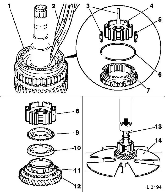
|
Disassemble Remove retaining ring (1) in front of drive gear (driving) from main shaft. Press of drive gear (driving) (3) with suitable drift (2) from main shaft in conjunction with KM-307-B (4).
 Important! Important! Always replace drive gears (driving and driven) in pairs | 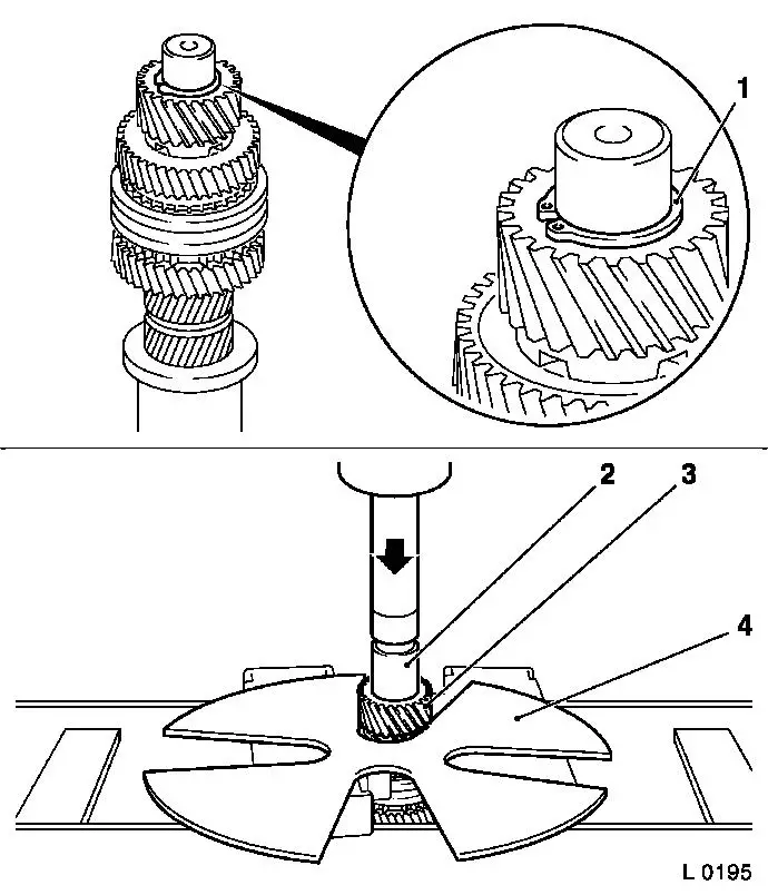
|
Disassemble Place KM-307-B (1) in groove of 4th gear (2). Press off 4th gear and spacer washer (4) with suitable drift (3) from main shaft in conjunction with KM-307-B. Remove needle bearing (5) (if in place), synchroniser ring (4th gear) (6), shifter collar (7), synchroniser spring and slide blocks from main shaft. Press off synchromesh body (9) 3rd/4th gear, synchroniser ring and 3rd gear (10) with suitable drift (8) from main shaft in conjunction with KM-307-B. | 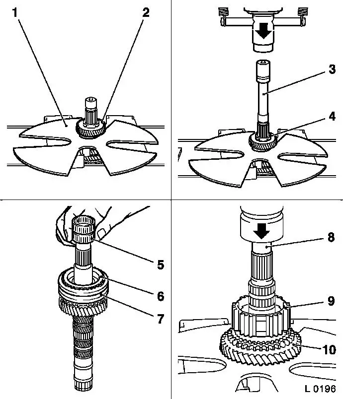
|
 Clean Clean Clean all parts.
 Inspect Inspect Immerse all parts in transmission fluid before installation. Check all removed parts for damage and wear, replace if necessary. Lubricate all bearing bore holes and seating surfaces with transmission fluid before installation. Transmission has 3 cone synchronisation for 1st/2nd gear:
2 Inner synchroniser rings
4 Outer synchroniser rings
| 
|
Notice: Synchromesh body assembly 1st/2nd gear and 3rd/4th gear can only be pressed onto main shaft in assembled state.
 Assemble Assemble Insert synchromesh body (3) into shifter collar (2). Insert slide blocks (1 and 5) with the open end toward synchromesh body. Insert synchroniser spring (4); ensure that the correct end of synchromesh body raises (arrow) for correct installation position. If this is not the case, turn synchroniser spring 180 ° and reinstall. Offset end of synchroniser engages in a slide block. | 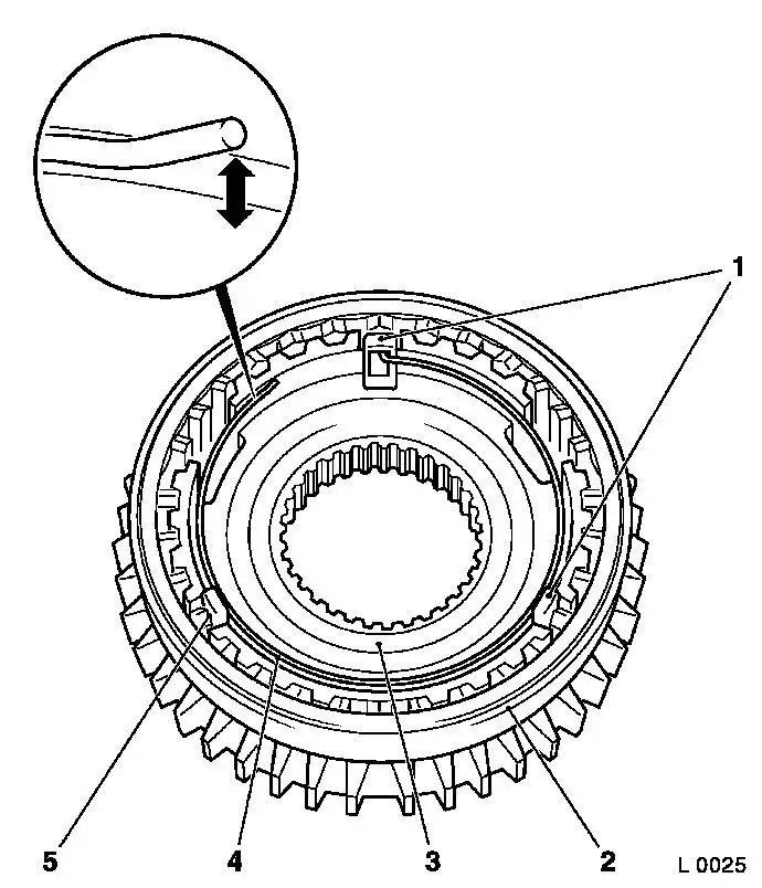
|
Assemble If present: Attach needle bearing (2) for 3rd gear to main shaft (1). Push 3rd gear (3) onto main shaft from drive gear side so that cone (arrow) points towards the drive gear. Place synchroniser ring (4) onto 3rd gear cone. Press synchromesh body assembly for 3rd/4th gear (6) with KM-277 (5) onto main shaft. | 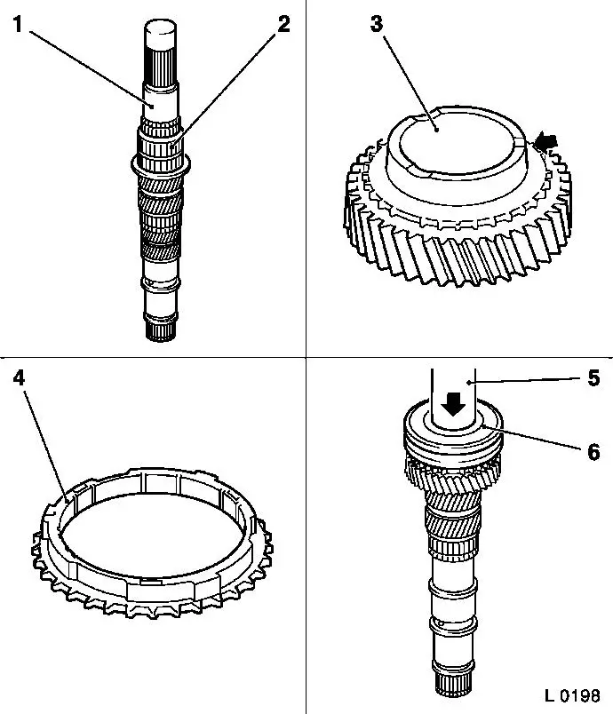
|
Assemble If present: Attach needle bearing for 4th gear to main shaft. Attach synchroniser ring (3) and 4th gear (2) to main shaft. Place spacer washer (1) on main shaft with four grooves (arrows) pointing towards 4th gear. Press drive gear (5) onto main shaft so that collar faces spacer washer - use KM-311/2 (4). Insert new retaining ring (6) in front of drive gear. Notice: Always replace drive gears in pairs. | 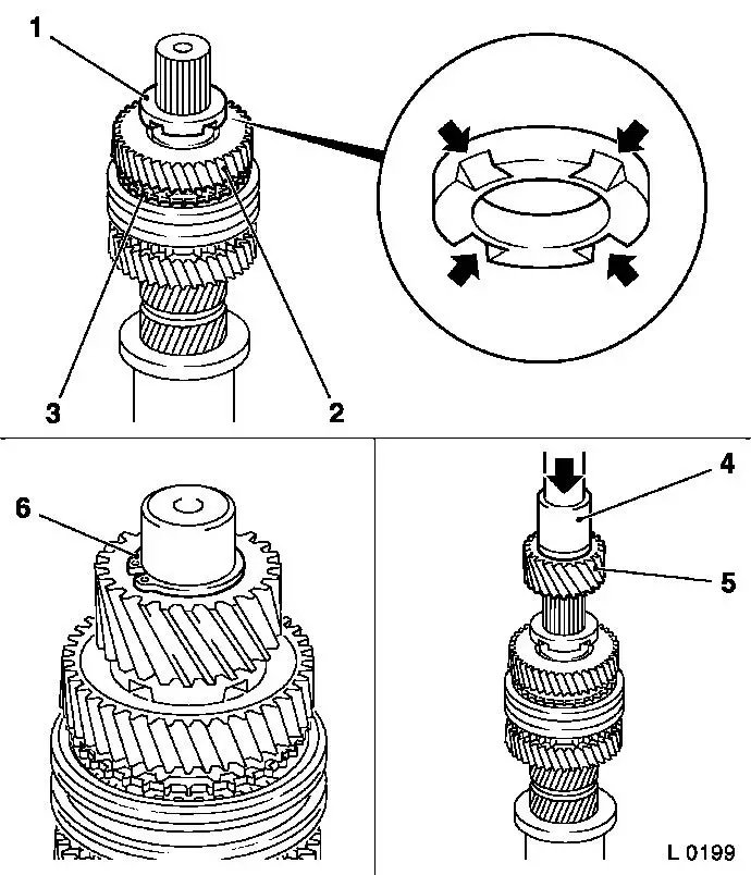
|
Assemble Push 2nd speed gear (4) onto main shaft. Place synchroniser ring (3) onto gear cone so that lugs are located in the grooves of the gear. Place intermediate ring (2) on inner synchroniser ring. Place outer synchroniser ring (1) onto intermediate ring so that grooves are seated on lugs of inner synchroniser ring. Place synchromesh body assembly (5) on main shaft. Press synchromesh body assembly with KM-277 (6) onto main shaft so that lugs of outer synchroniser ring align with grooves in synchromesh body. Groove (arrow) of shift fork points towards ball bearing seat. Insert new retaining ring (8) for 1st/2nd gear synchromesh body with ring pliers (7). | 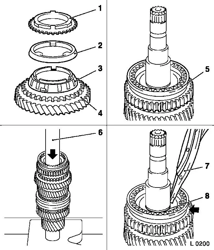
|
Assemble Place outer synchroniser ring (3) with lugs in grooves of synchromesh body (4). Place intermediate ring (2) on outer synchroniser ring. Place inner synchroniser ring (1) onto intermediate ring so that lugs engage in grooves of outer synchroniser ring. If present: Position 1st gear needle bearing (5) on main shaft. Push first speed gear onto needle bearing so that the grooves are seated on the lugs of the intermediate ring. Place output shaft (8) on 1st speed gear (10). Set spacer washer (7) on needle bearing. Place new retaining ring (9) with long legs (for main shaft to end shield) on 1st speed gear. Press ball bearing (6) onto main shaft with KM-334 (11). | 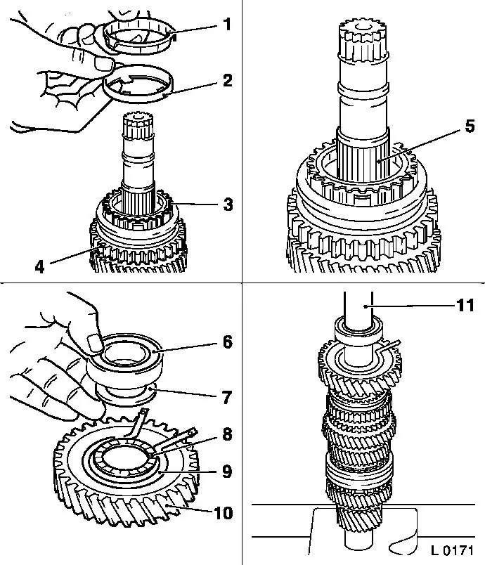
|
Inspect All speed gears must easily be turned.
 Install, Connect Install, Connect Install main shaft - see operation "End Shield, Disassemble and Assemble (F 13)". Install end shield (1) in transmission - see operation "Gasket for End Shield, Replace". Install end shield cover (2) - see operation "Gasket for End Shield Cover, Replace". Install reversing lamps switch (4) with new seal ring - tightening torque 20 Nm / 15 lbf. ft. Install cover (3) for shift mechanism - see operation "Cover for Shift Mechanism, Remove and Install and / or Seal". | 
|
|
