|
Both Camshafts, Remove And Install (Z 17 DTH, with
Air Conditioning, LHD)
 Remove Remove
Important: On vehicles with ESP -
the steering angle sensor loses its basic adjustment each time the
battery is disconnected. It must be recalibrated
|
| 2. |
Disconnect battery
|
| 3. |
Detach front right wheel
|
| 4. |
Remove air cleaner housing
|
| 5. |
Remove engine control unit (1)
| • |
Disconnect 2 wiring harness plugs
|
|
|
|
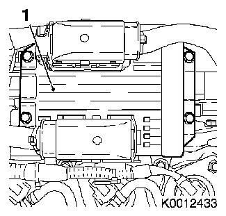
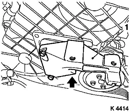
| 6. |
Detach engine control unit bracket (1)
|
|
|
| 7. |
Detach bracket (1) of engine control unit bracket
|
|
|
| 8. |
Remove engine management wiring harness
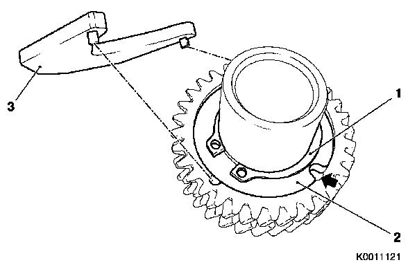
| • |
Disconnect wiring harness plug
| – |
Coolant temperature sensor (4)
|
| – |
Throttle valve module (2)
|
| – |
Exhaust gas recirculation valve (3)
|
| – |
Changeover valve solenoid valves
|
|
|
|
|
| 9. |
Detach charge air hose from throttle valve module
|
| 10. |
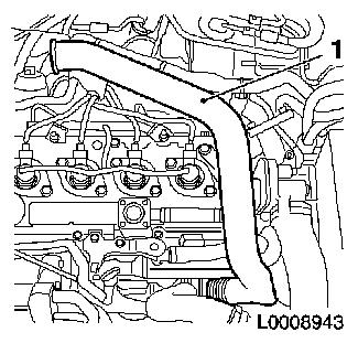
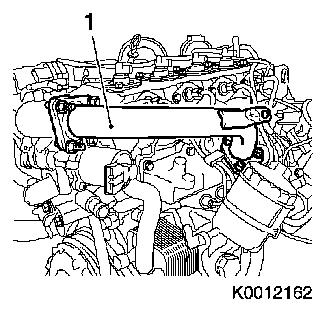
Remove air intake pipe (1)
| • |
Detach engine vent hose
|
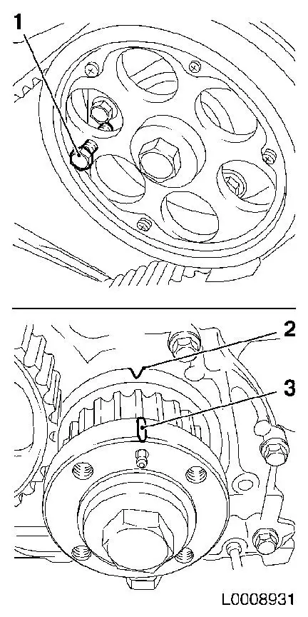
|
|
|
| 11. |
Remove charge air pipe (1)
| • |
Unscrew and remove 3 stud bolts
|
|
|
|
| 12. |
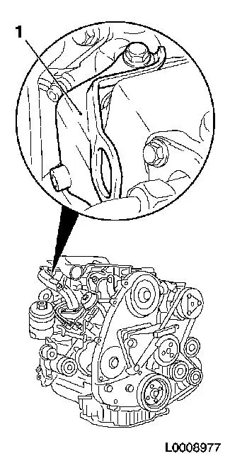
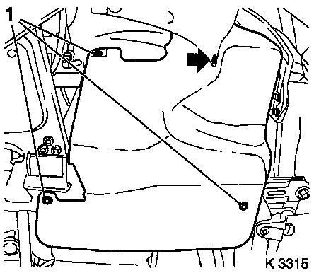
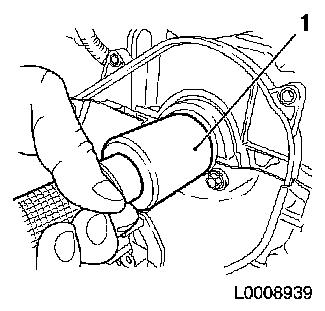
Remove rear left engine transport shackle (1)
|
|
|
| 13. |
Loosen upper oil dipstick guide tube
|
| 15. |
Remove right front wheel
|
| 16. |
Remove ribbed V-belt cover
|
|
|
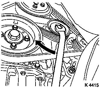
| 17. |
Loosen coolant pump ribbed V-belt pulley (1)
|
|
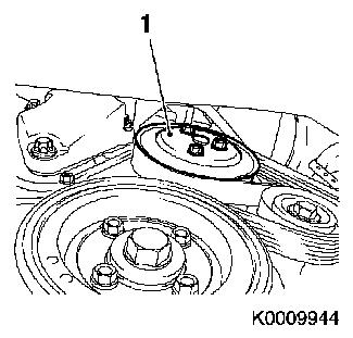
|
| 18. |
Remove ribbed V-belt
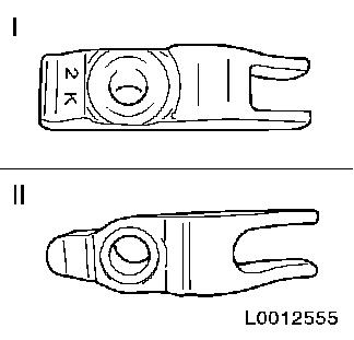
| • |
Tension ribbed V-belt tensioner in direction of arrow
|
| • |
Use KM-913-A
Note: Mark running
direction.
|
|
|
|
| 19. |
Detach starter wiring harness
|
|
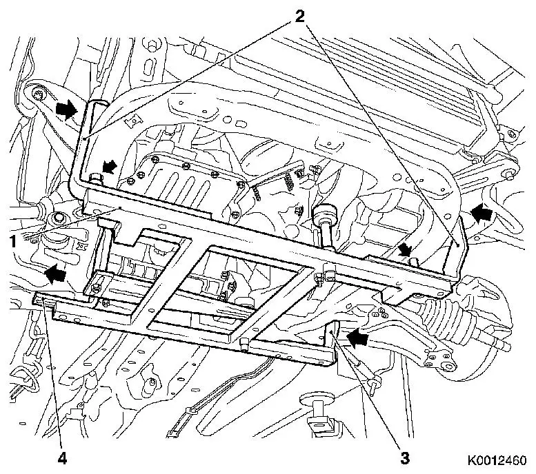
| 20. |
Attach KM-6394 (1)
| • |
Position KM-6394 at the front on the
front axle body
Note: Both locating
pins (arrows) must be seated in the hole in the front axle body
|
| • |
Push front bracket (2) in the direction of the arrow
|
| • |
Place rear bracket (4), right hand side, on front axle body
|
| • |
Attach rear bracket (3), left hand side
|
|
|
|
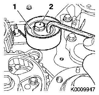
| 21. |
Install support
| • |
On KM-6394
| – |
Adjust bracket (2) for support
|
|
|
| 22. |
Adjust 3x support
| • |
Transmission side
Note: Turn spindles
until mounts (3) are positioned at guide journals free of play
|
| • |
Engine timing side
| – |
Insert journal of the support in the bore of the cylinder block
free of play (arrow)
|
|
|
|
|
| 24. |
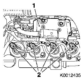
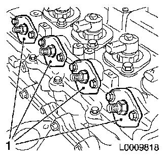
Remove 2 high pressure line spacers (2)
Note: Mark installation
position
|
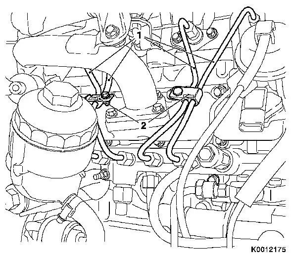
| 25. |
Detach 4 high-pressure lines (1)
|
|
| 26. |
Detach outer fuel return line (1)
| • |
Release retaining clamp (arrow)
|
|
|
|
|
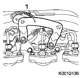
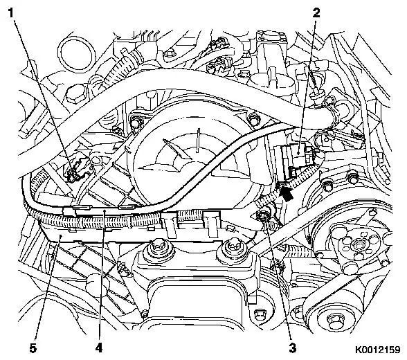
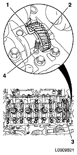
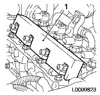
| 27. |
Remove wiring trough
| • |
Unclip wiring trough (5)
|
| • |
Disconnect 2 wiring harness plugs
| – |
Charge pressure sensor (1)
|
|
|
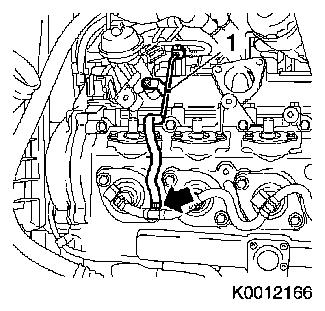
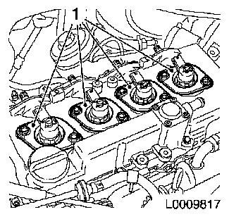
| 28. |
Remove camshaft sensor
|
|
| 29. |
Remove right engine damping block (1)
|
|
|
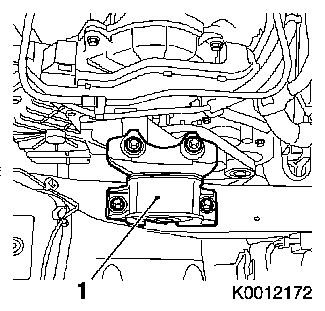
| 30. |
Detach right engine bracket (1)
| • |
Unscrew 3 bolts
Note: Lower bolt cannot
be removed.
|
| • |
With right engine bracket adapter
|
|
|
|
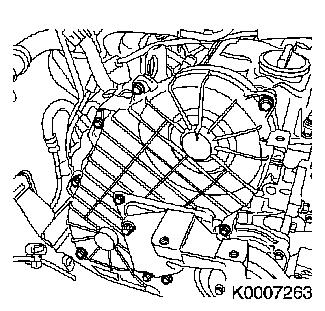
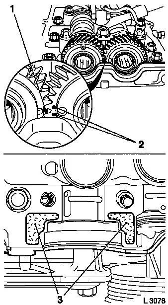
| 31. |
Remove upper toothed belt cover
Important: Take care not to
damage the increment counter on the camshaft sprocket when removing
the upper toothed belt cover
|
| • |
Unscrew 8 bolts
Note: Note dissimilar
bolt lengths
|
|
|
|
| 33. |
Detach coolant pump ribbed V-belt pulley
|
| 34. |
Remove torsional vibration damper (1)
|
|
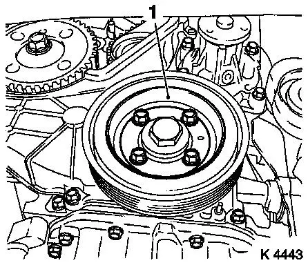
|
| 35. |
Detach lower part of toothed belt cover
|
|
|
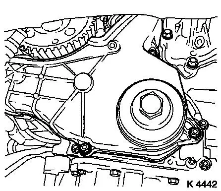
| 36. |
Remove right engine bracket
Note: Remove together
with engine bracket adapter.
|
| 37. |
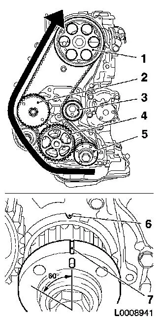
Set 1st cylinder to TDC
| • |
Turn crankshaft evenly until TDC fixing bolt (1) can be screwed
in
Note: Mark (3) on
toothed belt drive gear must align with mark (2) on oil pump
cover
|
|
|
|
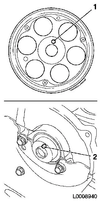
| 38. |
Remove toothed belt
| • |
Loosen bolt of toothed belt tension roller (2)
|
| • |
Rotate toothed belt tension roller (1) anticlockwise approx.
90°
|
| • |
Tighten bolt of toothed belt tension roller
|
|
|
|
| 39. |
Turn crankshaft
| • |
Rotate crankshaft against the direction of engine rotation to
60° BTDC
|
|
| 41. |
Detach camshaft pulley
| • |
Unscrew TDC fixing bolt (1)
|
| • |
Use KM-6347 (3) in combination with
KM-956-1 (2)
|
|
|
|
| 42. |
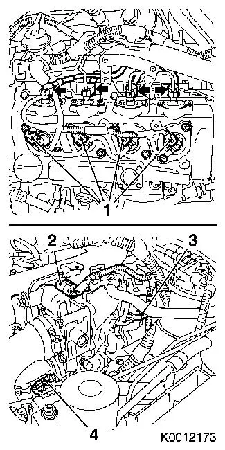
Detach 4x fuel return line (1)
| • |
From injector
| – |
Release 4x retaining clamp (arrow)
|
|
|
|
|
| 43. |
Remove rear right engine transport shackle
|
| 44. |
Remove 4x seal, connection for injector (1)
|
|
|
| 45. |
Remove 4 injector seal (1)
|
|
|
| 46. |
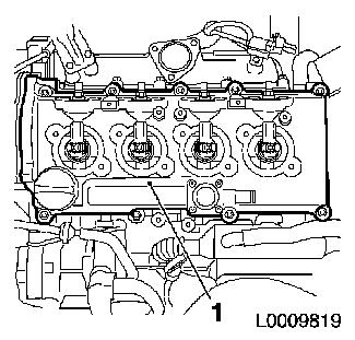
Remove camshaft housing cover (1)
Important: Do not damage
components
|
| • |
Unscrew 10 bolts
|
| • |
Unscrew and remove bolt
|
|
|
|
| 47. |
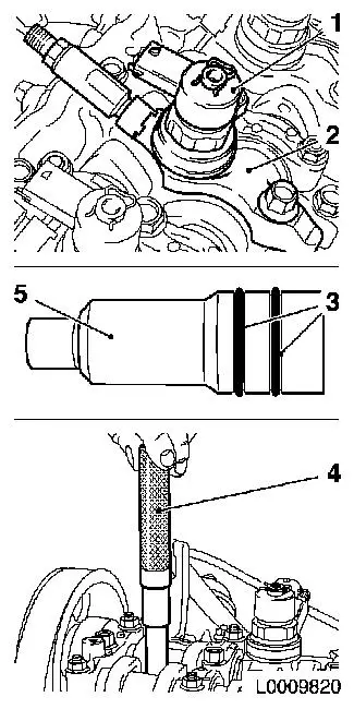
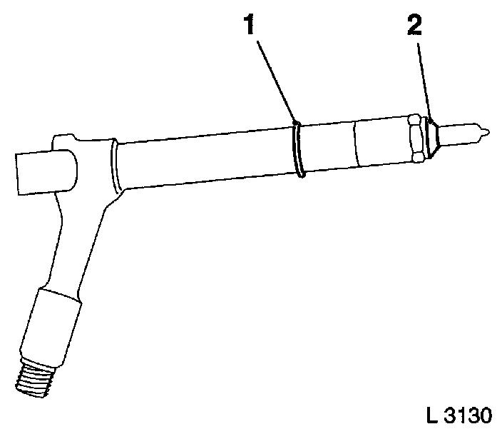
Remove 4x injector (1)
Note: Mark the
injectors. If the heat insulation sleeve (5) is pulled out together
with the injector during removal, the gaskets (3) must be replaced
and the heat insulation sleeve driven into the cylinder head using
KM-6357 (4)
|
|
|
| 48. |
Check injector bracket
Note: If an old
injector bracket was installed, it must be replaced with a new
one
- New injector bracket
- Old injector bracket
|
|
|
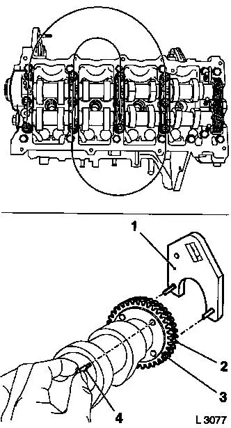
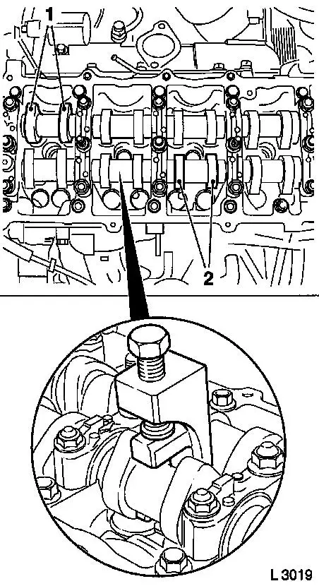
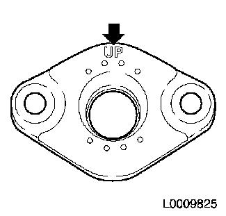
| 49. |
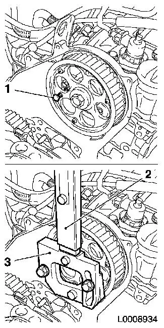
Lock exhaust camshaft sprockets
| • |
Remove camshaft bearing cap 5 (3)
|
| • |
Using KM-6092-10 (1), lock
compensating sprocket, exhaust camshaft (2), with exhaust camshaft
sprocket (4) so that it cannot turn
|
|
|
|
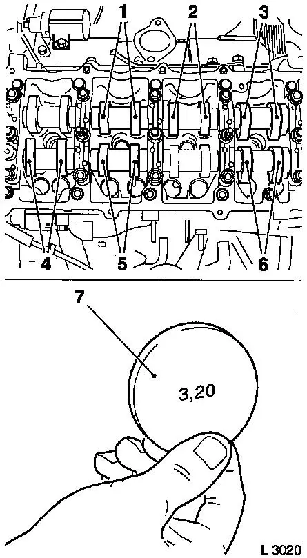
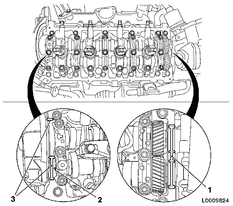
| 50. |
Remove 2x camshaft
Note: Check mark on
bearing cap before dismantling the camshafts
| • |
Ease the camshaft bearing covers in stages from 1/2 to 1 turn
in a spiral in the order shown
Note: When replacing
the exhaust camshaft, the exhaust camshaft compensating sprocket
(2) must be pretensioned with KM-6092 (1)
and connected to the exhaust camshaft sprocket (3) with locating
pin KM-6092-10 (4)
|
|
|
|
| 51. |
Remove camshaft seal ring (1)
|
|
|
| 52. |
When replacing: clamp exhaust camshaft in vice
|
|
| 53. |
When replacing: Fix tooth backlash compensator of exhaust
camshaft
| • |
Use KM-6092 (3)
Note: Turn tooth
backlash compensator until pin can be inserted in fixing hole
(arrow)
|
|
|
| 54. |
When replacing: remove exhaust camshaft from vice
|
| 55. |
Clean sealing surfaces
|
 Install
| 57. |
Install 2x camshaft
Important: When installing the
camshafts, care must be taking that the mark (1) on the exhaust
camshaft sprocket is between the two marks (2) for the intake
camshaft sprocket and that the marks are approximately at the same
level as the upper edge of the camshaft housing
|
| • |
Insert camshaft in camshaft housing
Note: Coat bearing
positions with engine oil
|
| • |
Apply surface sealant (green) to the sealing surfaces (3) of
the 1st camshaft bearing cap
|
|
|
|
|
| 58. |
Tighten 2x camshaft
Note: Coat bearing
positions with engine oil.
| • |
Attach camshaft bearing caps 1 - 4 to camshaft housing
Note: Arrows on bearing
caps point towards engine timing side.
|
| • |
Remove KM-6092-10 from exhaust
camshaft sprocket and attach camshaft bearing cap 5
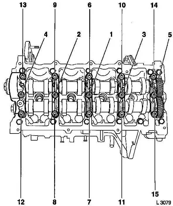
|
| • |
Tighten camshaft bearing covers in the sequence illustrated, 1
- 15, in stages of 1/2 to 1 turn
| – |
Tighten 10 nuts 21.6 Nm
|
| – |
Tighten 5 bolts 26.5 Nm
|
|
|
|
| 59. |
Install camshaft seal ring
| • |
Drive in until flush using KM-656
(1)
|
|
|
|
Warning: The different camshaft
sprockets (with different part numbers) have different torques for
the camshaft sprocket bolt.
|
| 60. |
Attach camshaft sprocket with part number 97320335
| • |
Camshaft journal (2) must engage in the bore in the camshaft
sprocket (1)
|
| • |
Use KM-6347 in combination with KM-956-1
|
| • |
Install TDC-fixing bolt
|
|
| 61. |
Attach camshaft sprocket with part number 98021306
| • |
Camshaft journal (2) must engage in the bore in the camshaft
sprocket (1)
|
| • |
Use KM-6347 in combination with KM-956-1
|
| • |
Install TDC-fixing bolt
|
|
|
|
| 63. |
Rotate crankshaft to 1st cylinder TDC
| • |
Mark on toothed belt drive gear (3) must align with cast lug
(2) on oil pump cover
|
| • |
Screw in TDC fixing bolt (1)
|
|
|
|
| 64. |
Install toothed belt
Note: TDC locking bolt
must be installed in the camshaft sprocket and marking (6) and (7)
must align.
| • |
Position toothed belt
| – |
Toothed belt must be tensioned in the direction of the arrow
from the toothed belt drive gear (5) via the oil pump drive gear
(4), via the high pressure pump drive gear (2) to the camshaft
sprocket (1)
|
|
| • |
Loosen toothed belt tension roller (3)
|
| • |
Remove TDC locking bolt
|
| • |
Rotate crankshaft 60° against direction of engine
rotation
|
| • |
Tighten toothed belt tension roller 38Nm
|
|
|
|
| 65. |
Timing, Check
| • |
Turn crankshaft approx. 780° in direction of engine
rotation
|
| • |
Mark on toothed belt drive gear (3) must align with cast lug
(2) on oil pump cover
|
| • |
Screw in TDC locking bolt (1). If the TDC fixing bolt cannot be
screwed in, basic adjustment must be repeated.
|
| • |
Unscrew TDC fixing bolt
|
|
|
|
| 66. |
Attach right engine bracket
| • |
Insert lower bolt in the right hand engine bracket and right
hand engine bracket adapter
|
| • |
Fit right engine bracket with adapter
|
|
| 67. |
Attach lower part of toothed belt cover
|
| 69. |
Turn crankshaft
| • |
Turn crankshaft until cam pairs (1) and (2) point upwards
|
|
| 70. |
Check valve clearance
| • |
Using feeler gauge
Note: The valve play is
checked on a cold engine at room temperature
| – |
Test values: Intake valves/Exhaust valves (0.35 – 0.45
mm)
|
|
|
Important: Make sure that the
valves are not set when the piston is in "TDC". The valves could
strike the piston head
|
| 71. |
Adjust valve clearance
| • |
Turn cup tappet until tappet groove points outwards
|
| • |
Press down cup tappets using KM-6090
Note: Note different
tool versions for intake and exhaust valves
| – |
Mark – IN = Intake side
|
| – |
Mark – EX = Exhaust side
|
|
|
|
|
| 72. |
Example for determination of shim thickness:
|
1. Thickness of installed shim
|
3.15 mm
|
|
2. Measurement between cam and cup tappets
|
+ 0.45 mm
|
| |
= 3.60 mm
|
|
3. Nominal valve clearance
|
- 0.40 mm
|
|
| 73. |
Insert adjustment shim
| • |
Coat new shim (7) with engine oil and insert in cup tappet with
identification mark facing downwards
|
|
| 74. |
Turn crankshaft
| • |
In direction of engine rotation by 180°
| – |
Check and adjust valve pair (6) and (2)
|
|
| • |
In direction of engine rotation by 180°
| – |
Check and adjust valve pair (5) and (3)
|
|
| • |
In direction of engine rotation by 180°
| – |
Check and adjust valve pair (4) and (1)
|
|
| • |
The clearance of all adjusted valves must be re-checked
|
|
|
|
| 75. |
Detach accumulator
| • |
Unscrew 2x bolts 1 - 1 1/2 turns
|
|
| 76. |
Replace 8 injector seals
| • |
4 copper seal rings (2)
|
|
|
|
| 77. |
Install 4 injectors
| • |
Install 4x brackets
| – |
Align injectors with EN-48560 (1)
|
|
|
|
|
| 78. |
Fasten 4x accumulator high pressure lines to injectors
| • |
Hand-tighten 8x union nuts
|
|
| 79. |
Fasten 4x injectors
| • |
Tighten 4 bolts in three stages
|
|
|
|
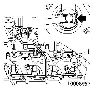
| 81. |
Remove 4x accumulator high pressure lines at injectors
| • |
Seal off connections of accumulator using suitable sealing
plugs
|
| • |
Seal off connections of injectors with protective caps
|
|
|
| 82. |
Install camshaft housing cover
Important: The oil hole (2) must
not be covered with adhesive sealing compound
|
| • |
Replace gasket
|
| • |
Apply adhesive sealing compound to sealing surfaces (1) and
(3)
|
| • |
Tighten 10 bolts 9.8 Nm
|
|
|
| 83. |
Fit 4 injector seals
Note: Coat with engine
oil
|
| 84. |
Fit 4 injector connection seals
| • |
Replace 4 gaskets
Note: Note installation
position (arrow). Coat with engine oil
|
|
|
|
| 85. |
Install camshaft sensor
|
| 86. |
Install upper toothed belt cover
| • |
Tighten 8 bolts 9.8 Nm
Note: Note dissimilar
bolt lengths
|
|
| 87. |
Fasten right engine bracket
| • |
Tighten 2 upper bolts 40 Nm
|
|
| 88. |
Install right engine damping block
| • |
At engine bracket adapter
| – |
Tighten 2 bolts 60 Nm + 30° +
15°
|
|
|
| 89. |
Attach wiring trough
| • |
Connect 2 wiring harness plugs
|
|
| 91. |
Fasten right engine bracket
| • |
Tighten lower bolt 40 Nm
|
|
| 94. |
Attach coolant pump ribbed V-belt pulley
|
| 95. |
Install torsional vibration damper
|
| 96. |
Attach starter wiring harness
| • |
Electrically connect starter
|
| • |
Connect fuel pressure sensor wiring harness plug
|
|
| 97. |
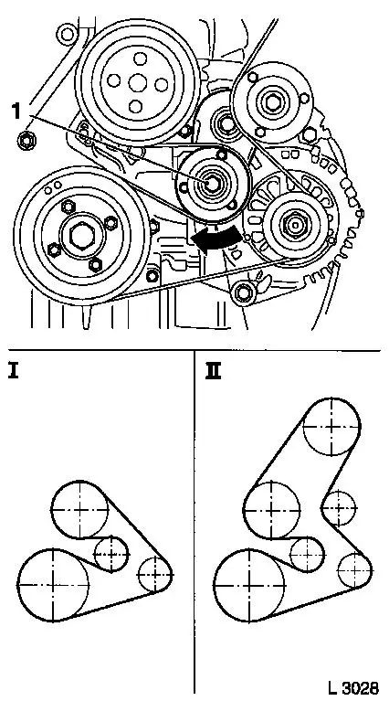
Install ribbed V-belt
Note: Observe running
direction and installation position
| • |
Tension ribbed V-belt tensioner (1)
| – |
I Ribbed V-belt without AC
|
| – |
II Ribbed V-belt with AC
|
|
|
|
|
| 98. |
Fasten coolant pump ribbed V-belt pulley
|
| 99. |
Install ribbed V-belt cover
|
| 101. |
Attach 4x fuel return line
| • |
To injector
| – |
Attach 4x retaining clamp
|
|
|
| 102. |
Attach outer fuel return line
| • |
Tighten banjo bolt 14.7 Nm
|
|
| 103. |
Fasten accumulator high pressure lines to injectors
| • |
Tighten 8x union nuts with KM-812 and
KM-6098
Note: First tighten
union nuts at the injectors and then at the accumulator
| |
Diameter
|
Torque
|
|
Version 1
|
6.00 mm
|
30 Nm
|
|
Version 2
|
6.35 mm
|
25 Nm
|
|
|
| 104. |
Install rear right engine transport shackle
|
| 105. |
Attach engine management wiring harness
| • |
Attach 14 wiring harness plugs
| – |
Coolant temperature sensor
|
| – |
Exhaust gas recirculation valve
|
|
| • |
Install wiring harness bracket
|
|
| 106. |
Install rear left engine transport shackle
| • |
Tighten 2 bolts 24.5 Nm
|
|
| 107. |
Install charge air pipe
| • |
Tighten 3 bolts 24.5 Nm
|
| • |
Tighten 3 stud bolts 24.5 Nm
|
|
| 108. |
Attach 2 wiring harness brackets
| • |
Route engine management wiring harness
|
|
| 109. |
Attach bracket of engine control unit bracket
|
| 110. |
Attach engine control unit bracket
|
| 111. |
Fit engine control unit
| • |
Connect wiring harness plug
|
| • |
Connect 2 combination plugs
|
|
Important: Ensure the
turbocharger is seated correctly
|
| 113. |
Install air intake manifold
|
| 116. |
Tighten front wheel 110 Nm
|
| 117. |
Attach charge air hose to throttle valve module
|
| 118. |
Install air intake pipe
| • |
Attach engine vent hose
|
| • |
Connect engine control unit wiring harness plug
|
|
| 119. |
Fasten upper dipstick guide tube
|
| 120. |
Install air cleaner housing
|
| 122. |
Check and correct engine oil level
| • |
Observe specified engine oil quantity
|
| • |
Start engine and allow to run until oil pressure telltale
extinguishes.
|
| • |
Check engine oil level, if necessary correct.
|
|
Important: Wear protective
goggles
|
| 123. |
Carry out leak test on high pressure system
Note: Engine must be at
operating temperature
| • |
Carry out actuator test (fuel leak)
|
| • |
Inspect high pressure system for fuel leak
|
|
| 124. |
Program volatile memory
|
| 125. |
Calibrate steering angle sensor
| • |
Turn on ignition
Note: Turn the steering
wheel once from the right stop to left stop.
|
|
|
