|
Remove and install crankshaft (Z 12 XE, Z 12 XEP,
Z 14 XEP, without air conditioning)
 Remove Remove
| 1. |
Remove and install engine - See operation J 340100 "Removing
and installing engine" in group "J"
|
| 2. |
Removing and installing manual transmission from engine - see
operation "J 340100-007 Manual transmission to engine, remove and
install"
|
| 3. |
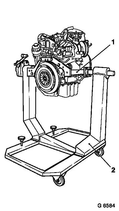
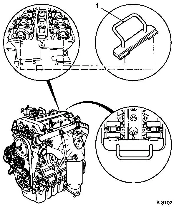
Install engine
| • |
Attach KM-412-18 (1) to engine
|
| • |
Install engine in KM-412 (2)
| – |
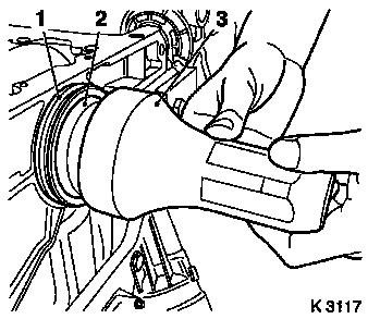
Tighten 8 bolted connections
|
|
|
| 4. |
Drain engine oil
| • |
Place collecting basin underneath.
|
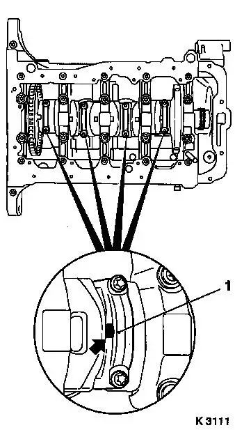
| • |
Remove oil filter housing cover
|
| • |
Remove oil filter element
|
|
|
|
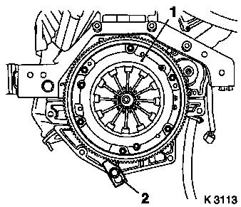
| 5. |
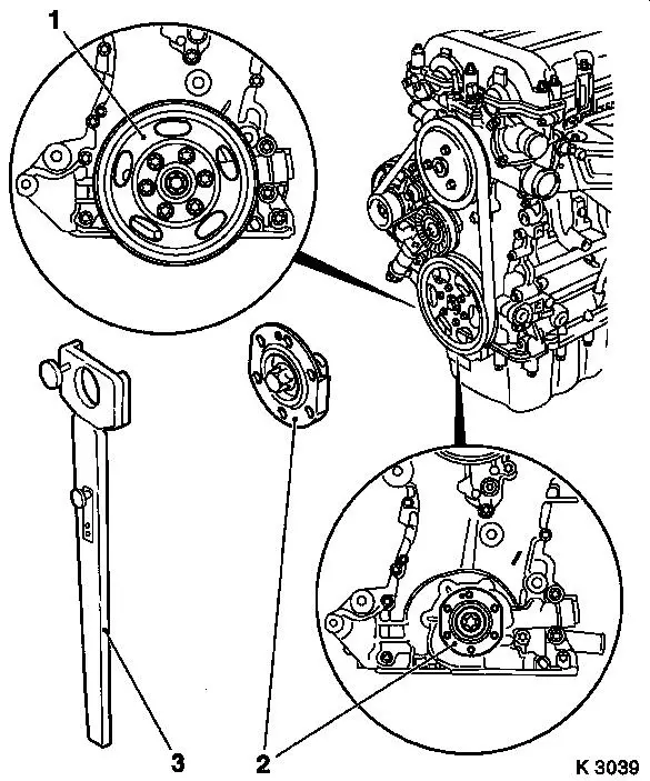
Detach clutch (1) - see operation "Remove and install thrust
plate and clutch disk" in group "K"
|
| 7. |
Detach right engine bracket
|
| 8. |
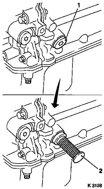
Install oil drain screw
|
|
|
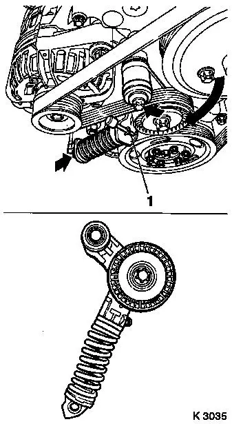
| 9. |
Remove ribbed V-belt
Note: Mark running
direction.
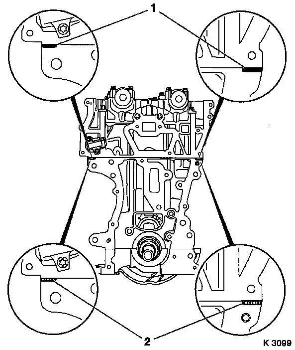
| • |
Tension ribbed V-belt tensioner in direction of arrow
|
| • |
Remove from crankshaft ribbed V-belt pulley
|
|
| 10. |
Detach coolant pump ribbed V-belt pulley
|
| 11. |
Detach crankshaft ribbed V-belt pulley
| • |
Counterhold at crankshaft hub bolt
|
|
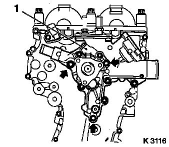
| 12. |
Detach ribbed V-belt tensioner
| • |
Unscrew 2 bolts (arrows)
|
|
|
|
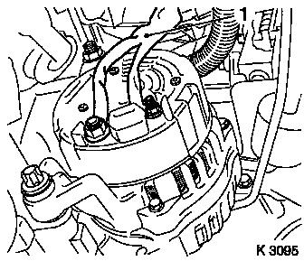
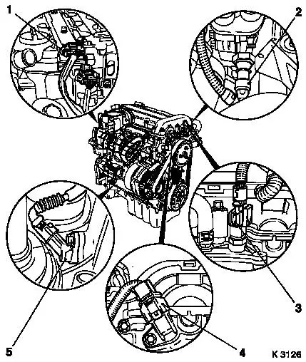
| 13. |
Remove alternator wiring harness (1)
|
|
|
| 15. |
Remove wiring harness for engine management
| • |
Disconnect wiring harness connector.
| – |
Oil pressure switch (2), coolant temperature sensor (3),
camshaft sensor (4) ignition module (1), crankshaft sensor (5)
|
|
|
| 16. |
Detach 3 coolant hoses from coolant pump
|
|
|
| 17. |
Detach coolant pump (1)
Note: Note guide
bushings during removal
| • |
Place collecting basin underneath.
|
| • |
Unscrew 9 bolts
Note: Pay attention to
different bolt lengths (arrows = short bolts)
|
|
|
|
| 18. |
Remove ignition module
| • |
Remove ignition module cover
|
| • |
Extract using KM-6009 (1)
Note: Do not tilt
|
|
| 19. |
Unscrew 4x spark plugs with KM-194-E
|
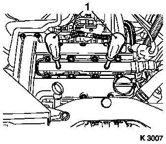
| 20. |
Detach cylinder head cover
| • |
Detach engine vent hose
|
|
|
|
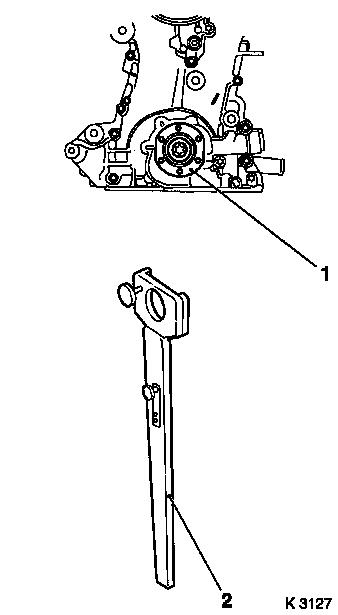
| 21. |
Loosen crankshaft hub bolt (1)
Note: Second person
required
| • |
Attach KM-956-1 KM-956-2 (2)
|
| • |
Counterhold KM-956-1 KM-956-2
|
|
|
|
| 22. |
Adjust camshafts
| • |
Uniformly rotate crankshaft in direction of engine rotation
with KM-956-1 KM-956-2 until KM-953 (1)
engages in camshaft groove as far as it will go
|
|
| 23. |
Remove crankshaft hub
Note: Pay attention to
installation position
| • |
Remove with KM-956-1 KM-956-2
|
|
|
|
| 25. |
Detach camshaft sensor (1)
|
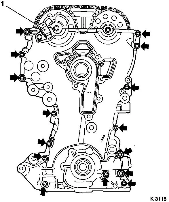
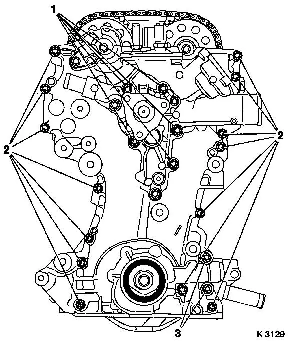
| 26. |
Remove timing case
| • |
Unscrew 15 bolts (arrows)
| – |
Pay attention to bolt lengths
|
|
| • |
Lever out timing case seal ring
Note: Do not damage
sealing surface
|
|
|
|
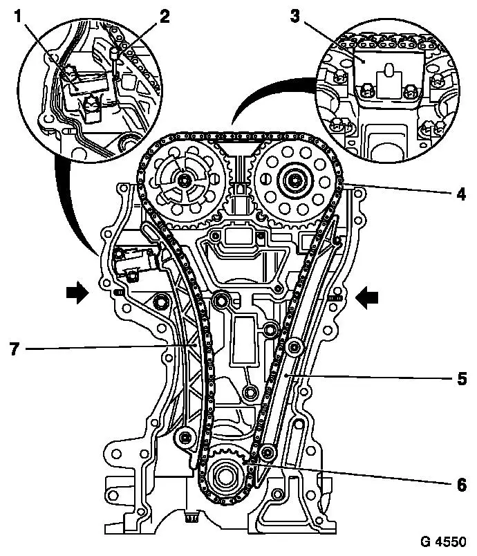
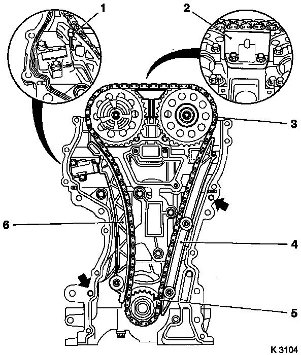
| 27. |
Remove chain drive
| • |
Loosen camshaft sprocket bolts
| – |
Counterhold camshafts at hexagonal section
|
|
| • |
Detach sliding rail (3), guide rail (5), tension rail (7) and
camshaft sprockets
|
| • |
Remove timing chain (4) with drive sprocket (6)
|
| • |
Remove timing case gasket.
|
|
|
|
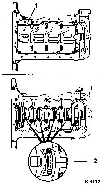
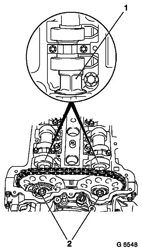
| 28. |
If present: detach oil baffle plate (1)
|
| 29. |
Remove crankshaft sensor
|
| 30. |
Remove con-rod bearing cap
| • |
Mark 4 con-rod bearing caps (2)
Note: Observe cylinder
sequence
|
Important: The mating surfaces of
the cod-rods and con-rod bearing caps form an individual fit and
must not be damaged or interchanged. Do not lay on mating
surfaces.
|
| • |
Remove 4 con-rod bearing caps
|
|
|
|
| 31. |
Remove crankshaft
| • |
Remove crankshaft bearing bridge
Note: Prise off
evenly
|
| • |
Remove crankshaft rear seal ring
|
| • |
Place crankshaft on wooden blocks
|
|
| 32. |
Remove crankshaft bearing shells
|
| 33. |
Remove crankshaft bearing shells
Note: Observe order
| • |
Mark crankshaft bearing shells
|
|
| 34. |
Remove con-rod bearing shells
Note: Observe order
| • |
Mark con-rod bearing shells
|
|
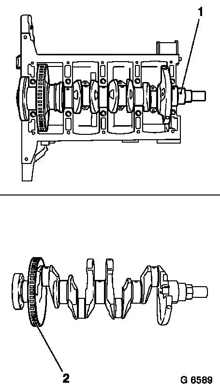
| 35. |
Remove crankshaft pulse pickup disc (1)
|
|
|
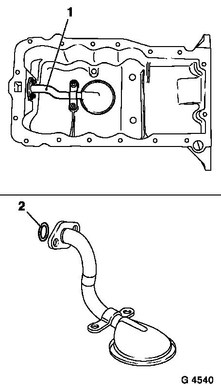
| 36. |
Remove oil intake pipe (1)
|
|
|
 Install
| 37. |
Clean sealing surfaces
| • |
Cylinder block, cylinder head, cylinder head cover, crankshaft
bearing bridge, chain drive, timing case, oil pan, coolant pump,
exhaust manifold
|
|
| 38. |
Inspect components
| • |
Cylinder block, cylinder head, cylinder head cover, crankshaft
bearing bridge, chain drive, timing case, oil pan, coolant pump
|
|
| 39. |
Check whether crankshaft bearing bridge is level using a
straightedge and a feeler gauge
|
| 40. |
Attach crankshaft pulse pick-up disk
|
| 41. |
Insert con-rod bearing shells
| • |
In con-rod, con-rod bearing cap
|
|
| 42. |
Insert crankshaft bearing shells
Note: Pay attention to
position of axial bearing (arrow)
| • |
Insert crankshaft bearing bridge into cylinder block
|
|
| 43. |
Insert crankshaft
| • |
Coat crankshaft journal with engine oil
|
|
|
|
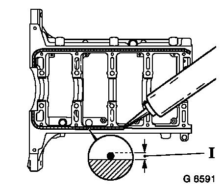
| 44. |
Install crankshaft bearing bridge
Note: Complete
installation work within 10 minutes
| • |
Apply sealant to outer edge of groove (dimension I = 2 mm)
Note: Do not apply
sealant in groove
|
| • |
Tighten 10 bolts (M8) 25 Nm +
60°
|
| • |
Tighten 12 bolts (M6) 10 Nm +
60°
|
|
|
|
| 45. |
Install rear crankshaft seal ring (1)
| • |
Coat sealing lip with silicone grease
|
| • |
Position KM-235-6 (2) on crankshaft
journal
|
| • |
Slide seal ring onto KM-235-6
|
| • |
Drive in until flush using KM-658-1
(3)
|
|
|
|
| 46. |
Attach con-rod bearing cap
Note: Bead on con-rod
bearing cap faces transmission side
| • |
Tighten 8 bolts (M6) 10 Nm + 60° +
15°
| – |
From engine number 19P13554 ( 13 Nm +
60° + 15° ) (M6.5)
|
|
|
|
|
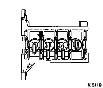
| 47. |
Lock crankshaft
| • |
Remove closure bolt (1)
|
| • |
Insert KM-952 (2)
| – |
Turn crankshaft uniformly until KM-952 engages
|
|
|
|
|
| 48. |
Replace timing case gasket
Note: Complete assembly
operations within 10 minutes
| • |
Apply sealant
| – |
Cut off excess elastomer of cylinder head gasket (1) and
replace with a 2 mm thick bead of silicone sealant
Note: If no excess
elastomer is present, the bead of silicone sealant can be applied
directly
|
| – |
Apply silicone sealant to joint between cylinder block and
crankshaft bearing bridge
|
|
|
|
|
| 49. |
Attach timing chain
Note: Ensure that guide
sleeves are correctly seated (arrows)
| • |
Position exhaust camshaft
|
| • |
Install timing chain (3)
|
| • |
Insert intake camshaft sprocket with phase sensor disc in
timing chain
| – |
Bolt in bolt
Note: It must be
possible to rotate phase sensor disk by hand
|
|
|
|
|
| 50. |
Attach timing chain tension rail (6)
Note: Ensure that
timing chain is correctly seated
|
| 51. |
Attach timing chain guide rail (4)
Note: Ensure that
timing chain is correctly seated
|
| 52. |
Attach timing chain sliding rail (2)
|
| 53. |
Release chain tensioner
|
|
|
| 54. |
Attach coolant pump
Note: Ensure that guide
sleeves are correctly seated (arrows)
| • |
Attach using short bolts (2)
|
| • |
Remove thermostat housing cover
|
|
|
|
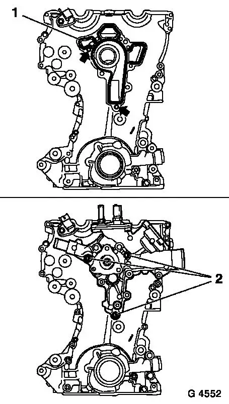
| 55. |
Attach timing case.
| • |
Tighten 5 bolts (1) (M6) 8 Nm
|
| • |
Tighten 14 bolts (2) (M6) 8 Nm
|
| • |
Tighten 2 bolts (3) (M10) 35 Nm
|
| • |
Attach thermostat housing cover
|
|
|
|
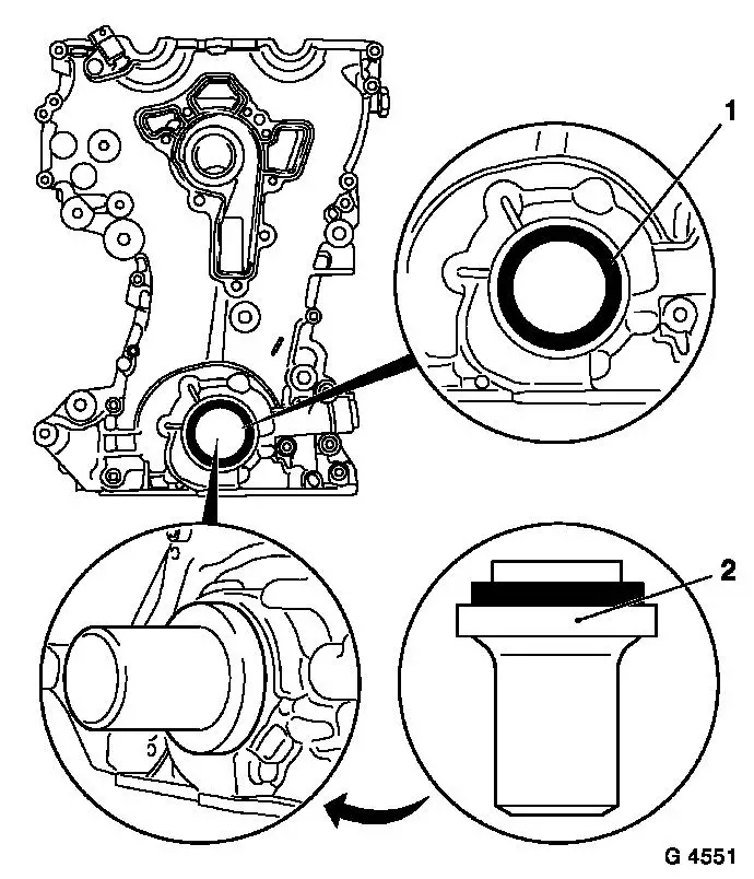
| 56. |
Replace crankshaft front seal ring (1)
| • |
Coat sealing lips with silicon grease
|
| • |
Drive in until flush using KM-960
|
|
| 57. |
Remove KM-952
Note: Retaining tools
must not be used for counterholding
|
|
|
| 58. |
Attach crankshaft hub
Note: Note crankshaft
hub (2) installation position - mark must point upwards
| • |
Counterhold with holder KM-956-1
KM-956-2 (3)
Note: Second person
required
|
| • |
Tighten bolt 150 Nm + 45°
|
| • |
Detach KM-956-1 KM-956-2
|
|
| 59. |
Attach crankshaft ribbed V-belt pulley (1)
| • |
Counterhold at crankshaft hub bolt
|
|
|
|
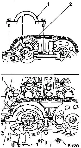
| 61. |
Attach KM-954 (1)
| • |
Rotate phase sensor disk (2) until KM-954 can be attached to timing case
|
|
|
|
| 62. |
Fasten camshaft sprockets
Note: Tightening torque
of 10 Nm is used to secure the camshaft sprockets and the phase
sensor disk
| • |
Tighten 2 bolts (2) 10 Nm
Note: First tighten
intake camshaft sprocket bolt
| – |
Counterhold camshafts at hexagonal section (1)
|
|
|
| 63. |
Remove retaining tools
| • |
KM-952 , KM-953 , KM-954
|
|
| 64. |
Fasten camshaft sprockets
Note: Second person
required
| • |
Tighten 2 bolts 50 Nm + 60°
Note: First tighten
intake camshaft sprocket bolt
| – |
Counterhold camshafts at hexagonal section
|
|
|
|
|
| 66. |
Remove retaining tools
| • |
KM-952 , KM-953 , KM-954
|
|
| 67. |
If present: attach oil baffle plate
|
| 68. |
Attach oil pan
| • |
Align oil pan to cylinder block using straight edge
|
|
| 69. |
Attach closure bolt of crankshaft bearing bridge
|
| 70. |
Install crankshaft sensor
|
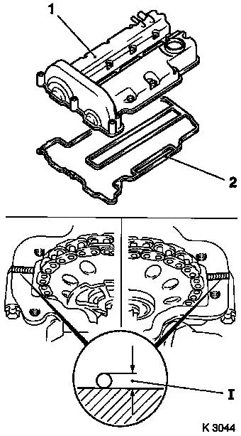
| 71. |
Attach cylinder head cover (1)
Note: Complete assembly
operations within 10 minutes
| • |
Renew gasket (2) and seal rings
|
| • |
Apply sealant (dimension I = 2 mm)
|
| • |
Attach engine vent hose
|
|
| 72. |
Install 4 spark plugs
| • |
Tighten using KM-194-E 25 Nm
|
|
| 73. |
Attach ignition module
| • |
Attach ignition module cover
|
|
|
|
| 74. |
Attach camshaft sensor
|
| 75. |
Attach 3 coolant hoses
|
| 76. |
Install engine management wiring harness
| • |
Connect 5 wiring harness plugs
|
|
| 78. |
Install alternator wiring harness
|
| 79. |
Attach ribbed V-belt tensioner
| • |
Tighten bolt (M8) 20 Nm
|
| • |
Tighten bolt (M10) 55 Nm
|
|
| 80. |
Attach coolant pump ribbed V-belt pulley
|
| 81. |
Install ribbed V-belt
Note: Observe running
direction and installation position
| • |
Release ribbed V-belt tensioner
|
|
| 82. |
Attach right engine bracket
|
| 83. |
Attach flywheel
| • |
Clean threads in crankshaft
|
| • |
Tighten 6 bolts 35 Nm + 30°
| – |
Apply screw locking compound
|
|
|
| 84. |
Attach clutch - see operation "Remove and install thrust plate
and clutch disk" in group "K"
|
| 85. |
Top up engine oil
| • |
Check engine oil level, if necessary correct.
|
|
| 86. |
Detach engine
| • |
Suspend engine on workshop crane
|
| • |
Detach from KM-412
| – |
Undo 8 screw connections
|
|
|
|
