|
Remove and refit engine (Z 10 XE, Z 10 XEP, with
air conditioning)
Note: KM-6394 must be used as of model year 04 instead of
KM-6169-1 .
 Remove Remove
| 1. |
On vehicles as of model year 04 with ESP - every time the
battery is disconnected, the steering angle sensor loses its basic
setting. It must be recalibrated.
|
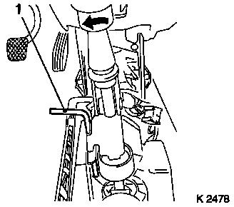
| 4. |
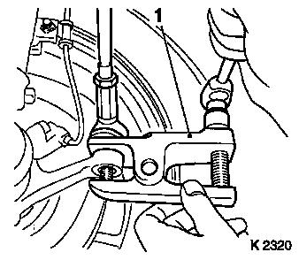
Detach steering intermediate shaft (1)
| • |
Remove lower clamp pin (2)
|
| • |
Steering in straight-ahead position
|
Important: Do not alter steering
wheel position
|
| • |
Remove steering intermediate shaft
|
|
|
|
| 6. |
Undo upper front panelling
|
|
|
| 8. |
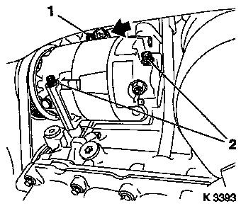
Undo lower front panelling
|
| 9. |
Detach front panelling
Note: Second person
required
| • |
Disconnect temperature sensor wiring harness plug
|
|
|
|
| 11. |
Remove ribbed V-belt cover
Note: In "ECO" model
variant remove lower engine compartment cover, see operation
"J481500 Removing and installing lower engine compartment cover
(ECO)" in group "A"
|
|
|
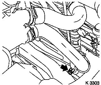
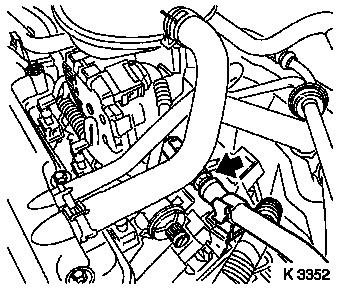
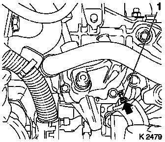
| 12. |
Drain coolant
| • |
Place collecting basin underneath.
|
| • |
Open drain bolt (arrow)
|
|
|
|
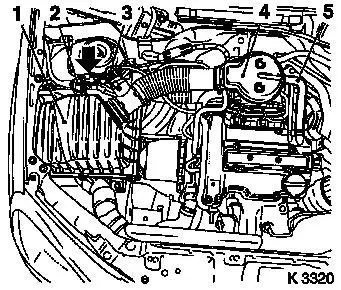
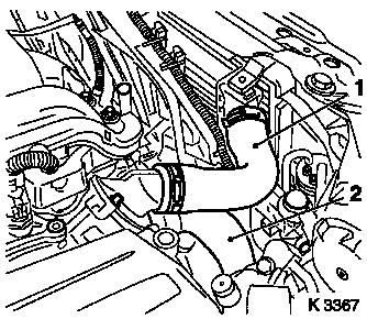
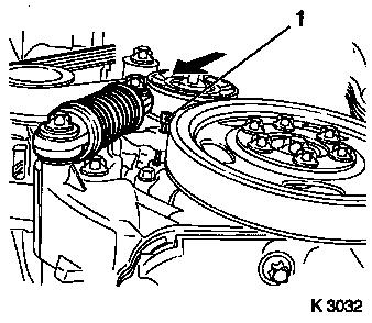
| 13. |
Remove air cleaner housing (1)
| • |
Disconnect 2 wiring harness plugs
| – |
Hot film mass air flow sensor (3), tank vent valve (2)
|
|
| • |
Remove suction pipe (4)
| – |
Detach engine vent hose (5)
|
|
| • |
On Z 10 XEP: Remove air intake hose
|
|
|
|
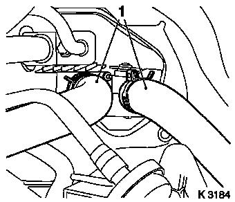
| 14. |
Detach 2x heater hoses (1) from heater core
|
|
|
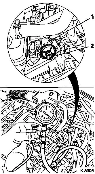
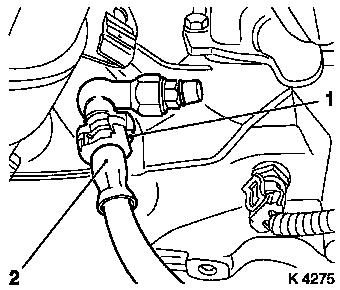
| 15. |
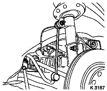
Release fuel pressure with KM-J-34730-91 at fuel rail (1)
Important: Observe safety
precautions and national regulations
|
| • |
Unscrew test connection protective cap (2)
Note: Test connection
for Z 10 XEP at upper fuel rail
|
|
|
|
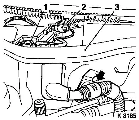
| 16. |
Remove fuel line
| • |
Unclip fuel line (arrow)
|
|
|
|
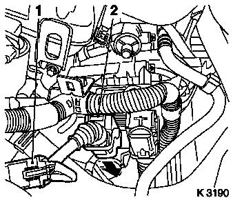
| 17. |
Unclip brake servo vacuum line (2)
|
| 18. |
Detach fuel evaporation hose (1)
|
|
|
| 19. |
Remove upper radiator hose (1)
|
| 20. |
Remove lower coolant hose (2)
|
|
|
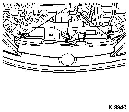
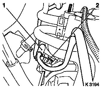
| 21. |
Remove wiring harness for engine management
| • |
Disconnect 2 wiring harness plugs
| – |
Reverse switch, combination plug (1)
|
|
| • |
Disconnect wiring harness plug of engine control unit (2)
| – |
Release in direction of arrow
|
|
| • |
Set wiring harness to one side
|
|
|
|
| 22. |
Disconnect engine wiring harness
| • |
Detach ground cable from battery.
|
| • |
Detach battery positive cable
|
| • |
Remove positive terminal (1)
|
| • |
Disconnect combination plug (2)
|
| • |
Remove cable harness and lay aside
|
|
|
|
| 23. |
Detach clutch actuation pressure hose
| • |
Remove cover of brake fluid reservoir
|
| • |
Top up brake fluid reservoir to "MAX" mark
|
| • |
Disengage retaining clip (1) with a screwdriver
|
| • |
Suspend pressure line for central release
Note: Collect escaping
brake fluid
|
|
| 26. |
Close coolant drain bolt
|
|
|
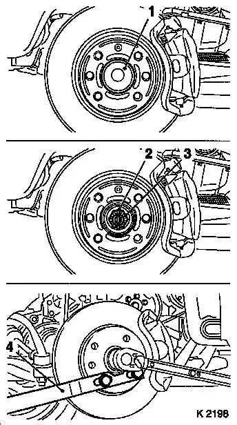
| 27. |
Loosen axle shafts
| • |
Detach 2x protective cap (1)
|
| • |
Remove 2 cotter pins (2)
|
| • |
Unscrew 2x nut (3)
| – |
Counterhold using KM-468-B
|
|
|
|
|
| 28. |
Detach tie rods from steering knuckle
| • |
Push off tie rods with KM-507-C
(1)
|
|
|
|
| 29. |
Detach swing arm from spring strut support tube
| • |
Remove 2 nuts
| – |
Counterhold with open-ended wrench
|
|
|
|
|
| 31. |
Press out axle shafts
|
|
|
| 33. |
Remove ribbed V-belt
| • |
Tension ribbed V-belt tensioner in direction of arrow
|
| • |
From compressor ribbed V-belt pulley
|
|
|
|
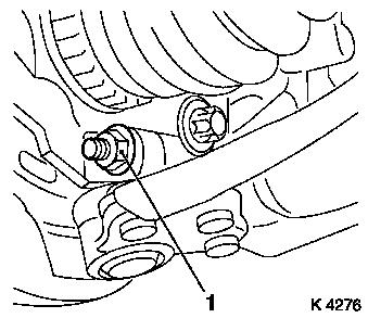
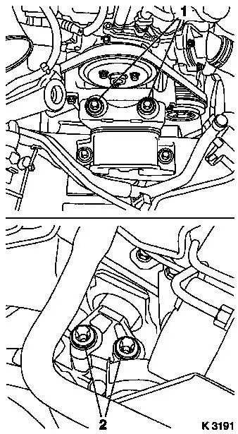
| 34. |
Remove compressor
Note: The air
conditioning system remains closed
| • |
Disconnect wiring harness plug (arrow)
|
| • |
Unscrew 3x bolts (1, 2)
| – |
Remove compressor heat shield
|
|
|
|
|
| 35. |
Remove exhaust system
| • |
Disconnect oxygen sensor (catalytic converter control) wiring
harness plug
|
| • |
Remove front exhaust pipe
|
|
| 36. |
Remove exhaust system
Note: Second person
required
|
|
|
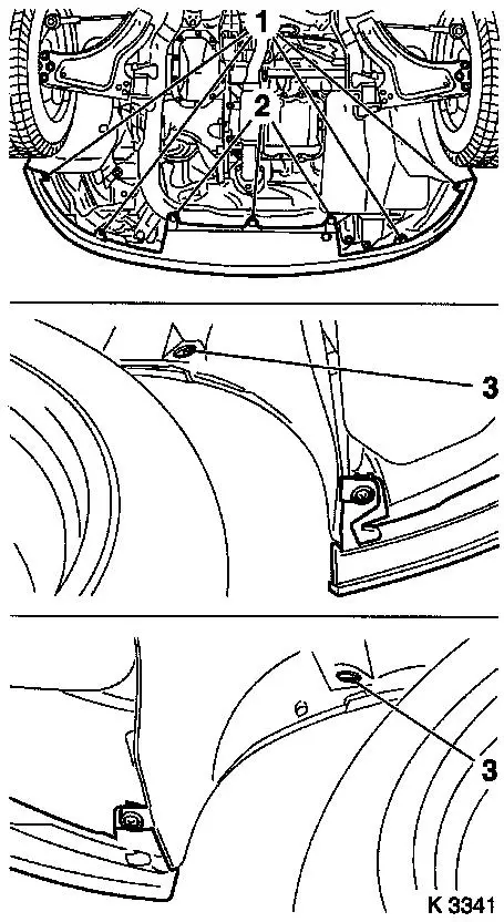
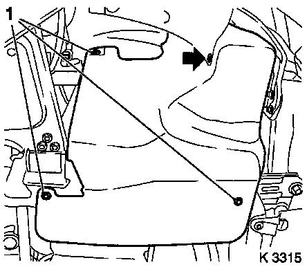
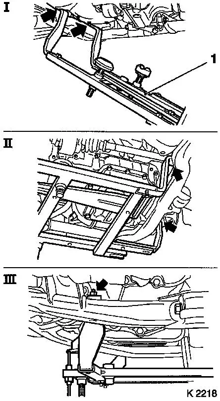
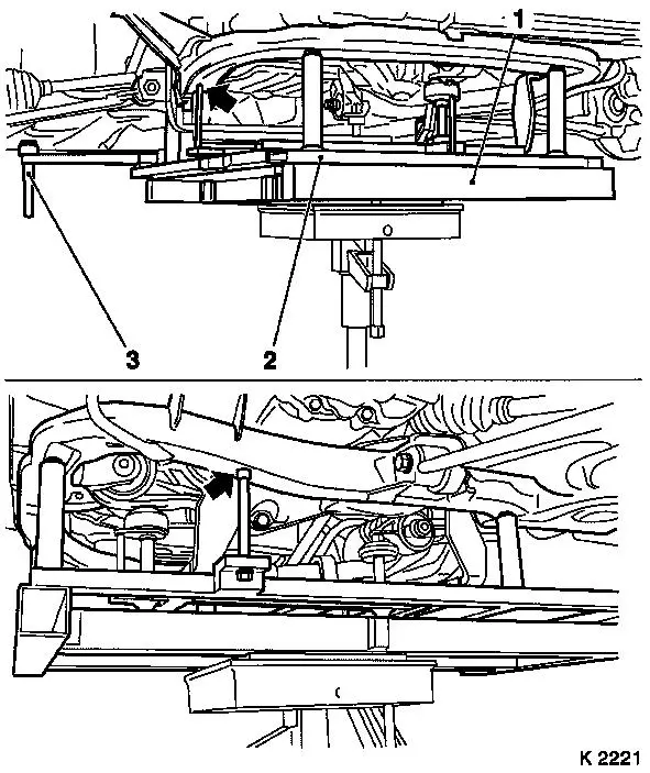
| 39. |
Attach KM-6169 (1)
| • |
Attach KM-6169 to left of front axle
body (arrows, illus. I)
| – |
Guide pin must be seated in bore in front axle body
|
|
| • |
Attach both right holders on the front axle body (arrows,
Illus. II).
| – |
Guide pin must be seated in bore in front axle body (arrow,
Fig. III)
|
|
|
|
|
|
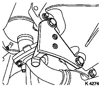
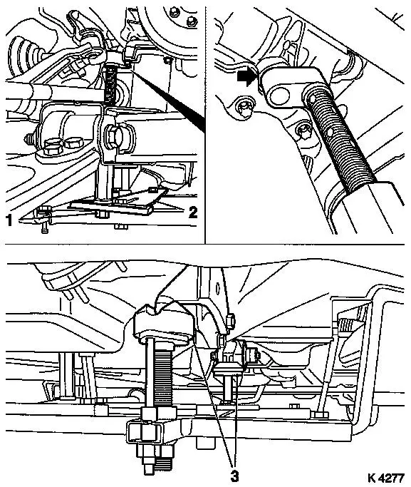
| 40. |
Attach connection to KM-6169
| • |
Adjust bracket (2) for support
|
|
| 41. |
Adjust supports
| • |
Transmission side
| – |
Turn spindles until mounts (3) are positioned at guide journals
free of play
|
|
| • |
Engine timing side
| – |
Insert journal of the support in the bore of the cylinder block
without play (arrow)
|
|
|
|
| 42. |
Remove adapter for right engine bracket
|
| 43. |
Detach left engine damping block adapter
|
|
|
|
| 45. |
Move in hydraulic jack with KM-904
(1)
|
| 46. |
Attach KM-6168 (2)
| • |
Position KM-6168 on KM-904
Note: Lower body
positioning pins (3)
|
| • |
Position KM-6168 beneath front axle
body without clearance
Note: Note centring
points in front axle body (arrows).
|
|
|
|
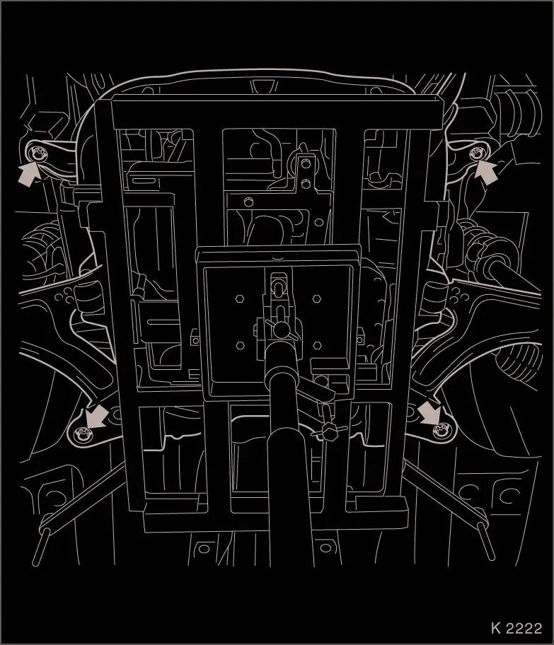
| 47. |
Release front axle body
Note: The removal of
the front axle body with an impulse or impact screwdriver is not
permitted
| • |
Unscrew 4 bolts (arrows)
|
|
| 48. |
Lower drive unit
Note: Second person
required
| • |
Carefully lower front axle body with engine and transmission
out of engine compartment from below
Note: Do not damage
attaching parts
|
|
| 50. |
Check threads of 4x lock nuts
Note: Check ease of
movement of lock nut threads before installing front axle body,
otherwise replace lock nuts
|
|
 Install
| 51. |
Install drive unit
Note: Body locating
pins fixed in raised position
|
| 52. |
Raise drive unit
Note: Second person
required
| • |
Carefully move front axle body with engine and transmission
into engine compartment (upwards)
Note: Do not damage
attaching parts
|
| • |
Insert body positioning pins in body positioning holes
|
|
| 53. |
Fasten front axle body
| • |
Tighten 4 bolts 90 Nm + 45° +
15°
|
|
| 54. |
Remove hydraulic jack
|
| 56. |
Secure left engine damping block adapter
|
| 57. |
Fasten right engine bracket adapter
| • |
Tighten 2 bolts 60 Nm + 45° +
15°
|
|
| 63. |
Fit compressor
| • |
Connect wiring harness plug
|
|
| 64. |
Install ribbed V-belt
Note: Observe running
direction and installation position
| • |
Relax ribbed V-belt tensioner with KM-6131
|
|
| 66. |
Attach exhaust system
Note: Second person
required
|
| 67. |
Attach exhaust system
| • |
Connect oxygen sensor (catalytic converter control) wiring
harness plug.
|
|
| 71. |
Attach swing arm
| • |
Tighten 2 nuts 65 Nm
| – |
Counterhold with open-ended wrench
|
|
|
| 73. |
Fasten axle shafts
| • |
Tighten 2 nuts 120 Nm
| – |
Counterhold using KM-468-B
|
|
| • |
Tighten 2 nuts 20 Nm + 90°
| – |
Counterhold using KM-468-B
|
|
| • |
Replace split pins
Note: If necessary,
unscrew the nut until a pin hole aligns with the next castle nut
groove
|
| • |
Install protective caps
|
|
| 74. |
Install ribbed V-belt cover
Note: With "ECO" model
variant - install lower engine compartment cover 
|
| 75. |
Position front panelling
Note: Second person
required
| • |
Install high-pressure headlamp washer hose
|
|
| 76. |
Fasten lower front panelling
| • |
Connect wiring harness plug
|
|
| 79. |
Fasten upper front panelling
|
| 80. |
Fasten front wheels
| • |
Tighten 8x bolts 110 Nm
|
|
| 81. |
Attach pressure line for central release
Note: Pressure line
must audibly engage
| • |
Bleed clutch actuation – see operation "Hydraulic Clutch
Actuation, Bleed " in group "K".
|
| • |
Screw on cover of brake fluid reservoir
|
|
| 82. |
Connect engine wiring harness
| • |
Connect wiring harness plug
|
| • |
Install positive terminal
|
|
| 83. |
Attach wiring harness for engine management
| • |
Connect 3 wiring harness plugs
|
|
| 84. |
Install lower radiator hose
|
| 85. |
Install upper radiator hose
|
| 86. |
Attach brake servo vacuum line
Note: Connection must
audibly engage
|
| 87. |
Attach fuel evaporation hose
|
| 88. |
Attach fuel line
| • |
Attach fuel line
Note: Fuel line must
audibly engage
|
|
| 89. |
Connect heater fluid hoses
|
| 90. |
Attach preheater hose for throttle valve module
|
| 91. |
Install air cleaner housing
| • |
On Z 10 XEP: Fit air intake hose
|
| • |
Attach engine vent hose
|
| • |
Clip in tank vent valve
|
| • |
Connect 2 wiring harness plugs
|
|
| 92. |
Install steering intermediate shaft
Note: Wheels in
straight-ahead position
| • |
Push on steering intermediate shaft
Note: The bore for the
clamp bolt must be on the flat-milled side of the stub axle
|
| • |
Adjust length compensator
| – |
Fasten with KM-6181 (1)
|
|
|
|
|
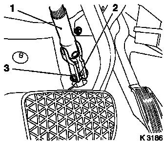
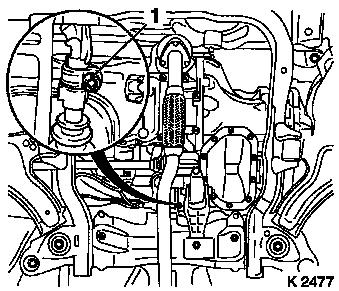
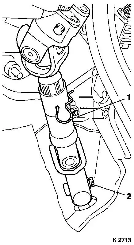
| 93. |
Locking transmission shift linkage
| • |
Unclip manual shift lever cover
|
| • |
Lock shift lever and shift lever housing with KM-527-A (1)
|
|
|
|
| 94. |
Lock transmission
| • |
Engage arresting pint (1) in adjusting bore of shift cover by
twisting the shift rod to the left
|
|
|
|
| 96. |
Fasten clamp
| • |
Tighten bolt (1) 12 Nm + 90° +
90° to 90° + 90° +
45°
|
|
|
|
| 98. |
Check transmission shift linkage
| • |
Remove adjusting pin KM-527-A
Note: Locking pin in
adjusting hole releases itself when the first gear selection in
direction "R" occurs
|
| • |
Clip in manual shift lever cover
|
|
| 100. |
Top up and bleed cooling system – see operation "Cooling
System, Top up and Bleed".
|
| 101. |
Program volatile memory
|
|