|
Oil Pump, Remove and Install (Z 18 XE, with Air
Conditioning, LHD)
Note: KM-6394 must be used as of model year 04 instead of
KM-6169-1 .
 Remove Remove
| 2. |
Disconnect battery
Note: In vehicles from
model year 04 onwards with ESP - the steering angle sensor loses
its basic adjustment each time the battery is disconnected and must
be recalibrated.
|
| 3. |
Remove engine cover.
| • |
Unscrew oil filler pipe cap
|
| • |
Screw on oil filler pipe cap
|
|
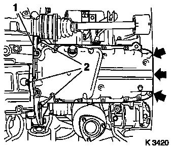
| 4. |
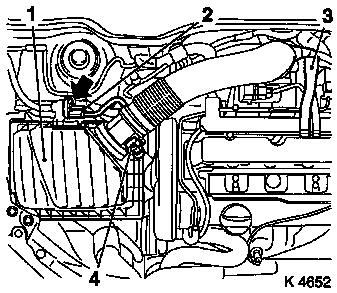
Remove air cleaner housing (1)
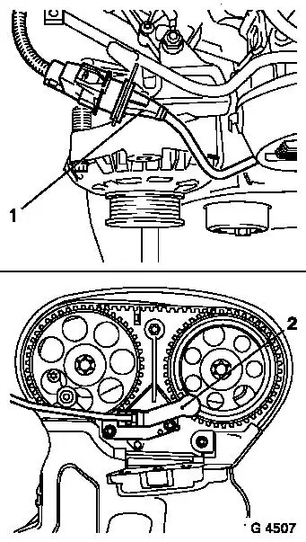
| • |
Disconnect 2 wiring harness plugs
| – |
Hot film mass air flow meter (4), tank vent valve (2)
|
|
| • |
Detach engine vent hose (3)
|
|
|
|
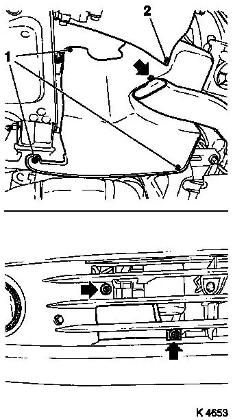
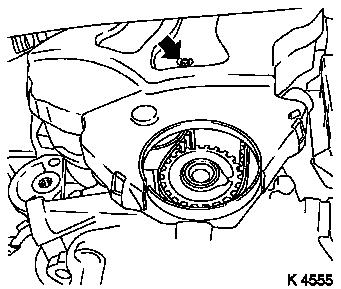
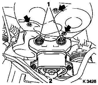
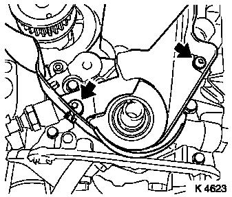
| 6. |
Remove right-hand air duct
| • |
Unscrew 3 bolts (arrows)
|
|
| 7. |
Remove ribbed V-belt cover
|
|
|
| 9. |
Detach front right wheel
|
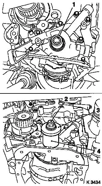
| 11. |
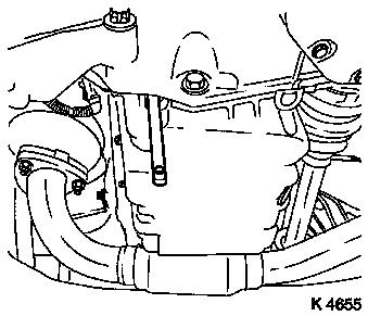
Remove right front wheel.
|
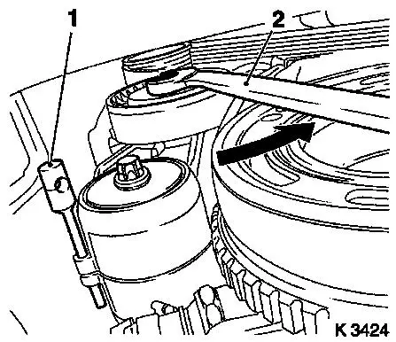
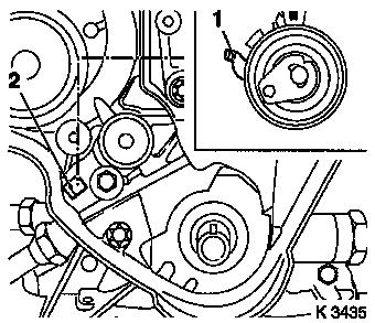
| 13. |
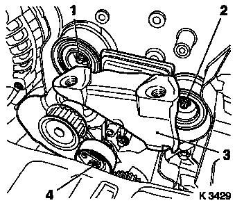
Remove ribbed V-belt
| • |
Tension ribbed V-belt tensioner in direction of arrow with
KM-913-A (2)
|
|
|
|
| 14. |
Remove ribbed V-belt tensioner
| • |
Tension ribbed V-belt tensioner.
|
| • |
Release ribbed V-belt tensioner
|
|
|
|
| 15. |
Detach crankshaft ribbed V-belt pulley
| • |
Prise front closure plug out of oil pan
|
|
|
|
| 16. |
Release lower part of toothed belt cover
| • |
Unclip from rear toothed belt cover
|
|
|
|
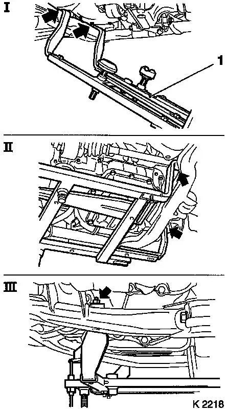
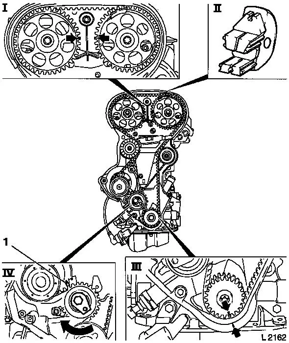
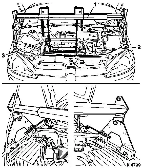
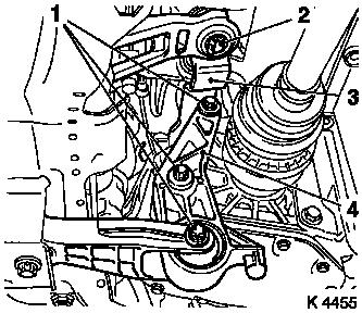
| 18. |
Attach KM-6169 (1)
| • |
Attach KM-6169 to left of front axle
body (arrows, illus. I)
| – |
Guide pin must be seated in bore in front axle body
|
|
| • |
Attach both right holders on the front axle body (arrows,
Illus. II).
| – |
Guide pin must be seated in bore in front axle body (arrow,
Fig. III)
|
|
|
|
|
|
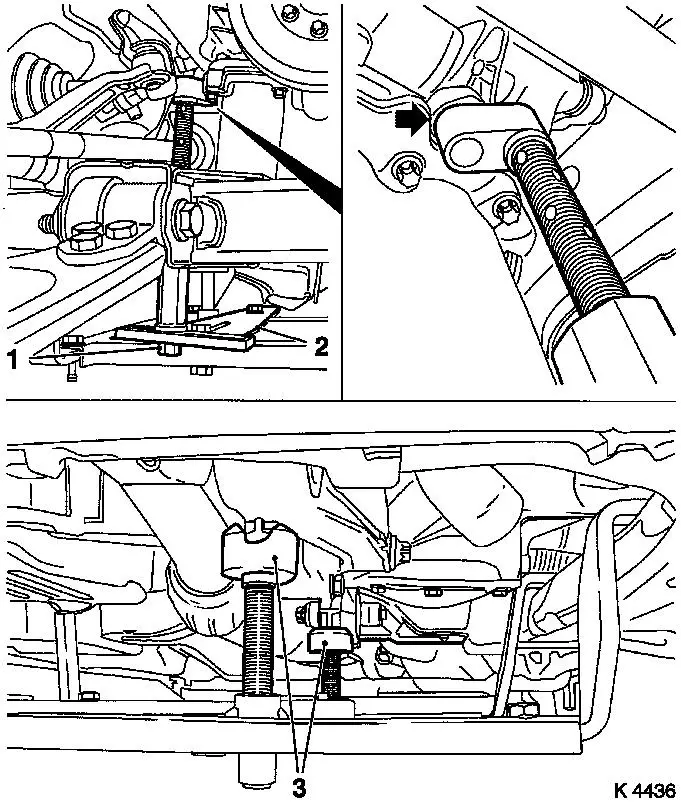
| 19. |
Install support
| • |
An KM-6169
| – |
Adjust bracket (2) for support
|
|
|
| 20. |
Adjust supports
| • |
Transmission side
| – |
Turn spindles until mounts (3) are positioned at guide journals
free of play
|
|
| • |
Engine timing side
| – |
Insert journal of the support in the bore of the cylinder block
without play (arrow)
|
|
|
|
| 22. |
Remove right engine damping block
| • |
Loosen engine bracket adapter
|
| • |
Loosen engine damping block
|
|
| 23. |
Remove upper part of toothed belt cover
| • |
Unscrew 3 bolts (arrows)
|
| • |
Unclip from rear toothed belt cover
|
|
|
|
| 24. |
Remove camshaft sensor (2)
| • |
Disconnect wiring harness plug (1)
|
|
| 25. |
Remove lower part of toothed belt cover
| • |
Unclip from rear toothed belt cover
|
|
|
|
|
| 26. |
Set 1st cylinder to TDC of combustion stroke
| • |
Install crankshaft V-belt pulley bolt
|
| • |
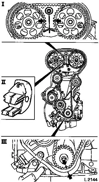
Set crankshaft to mark.
| – |
Marks on drive gear toothed belt and rear toothed belt cover
must align (III).
|
|
| • |
Fix camshaft sprockets in position.
| – |
Marks must be opposite one another and aligned with the top
edge of the cylinder head (I)
|
|
|
| 27. |
Remove toothed belt
| • |
Release toothed belt tension roller (IV)
| – |
Turn adjusting eccentric in direction of arrow (clockwise)
until pointer (1) of the toothed belt tension roller is located
just before left stop.
|
|
|
|
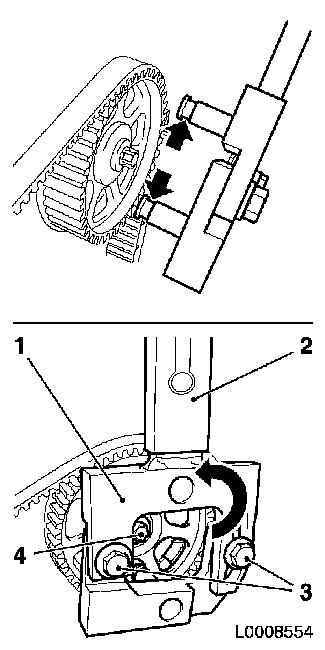
| 28. |
Remove camshaft sprocket on exhaust side
| • |
Use KM-6347 (1), KM-956-1 (2)
|
| • |
Attach KM-6347 , KM-956-1
| – |
Release fixing bolts (3) from KM-6347
|
| – |
Insert KM-6347 together with KM-956-1 into camshaft sprocket
Note: Grooves of KM-6347 must engage in camshaft sprocket
(arrows). Ensure correct seating.
|
|
| • |
Turn KM-6347 together with KM-956-1 in the direction of the arrow
| – |
Tighten 2 clamping screws
|
|
| • |
Loosen camshaft sprocket bolt (4)
|
| • |
Remove KM-6347 , KM-956-1
|
| • |
Unscrew camshaft sprocket bolt
|
|
|
|
| 29. |
Remove camshaft sprocket on intake side
| • |
Use KM-6347 (1), KM-956-1 (2)
|
| • |
Attach KM-6347 , KM-956-1
| – |
Release fixing bolts (3) from KM-6347
|
| – |
Insert KM-6347 together with KM-956-1 into camshaft sprocket
Note: Grooves of KM-6347 must engage in camshaft sprocket
(arrows). Ensure correct seating.
|
|
| • |
Turn KM-6347 together with KM-956-1 in the direction of the arrow
| – |
Tighten 2 clamping screws
|
|
| • |
Loosen camshaft sprocket bolt (4)
|
| • |
Remove KM-6347 , KM-956-1
|
| • |
Unscrew camshaft sprocket bolt
|
|
| 30. |
Remove intake side toothed belt guide roller
|
| 31. |
Remove exhaust side toothed belt guide roller
|
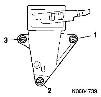
| 32. |
Remove right engine bracket (3)
|
| 33. |
Remove toothed belt tension roller
|
|
|
|
| 34. |
Use MKM-883-1 (1)
Note: Second person
required
|
| 35. |
Fasten MKM-883-1
Note: Observe
manufacturer's instructions
|
| 36. |
Attach engine
| • |
To right engine transport shackle (3)
|
| • |
To front left engine transport shackle (2)
Note: Fastening to
front left engine transport shackle serves only to stabilise the
engine
|
|
|
| 38. |
Remove toothed belt drive pulley
| • |
Unscrew crankshaft ribbed V-belt pulley bolt
|
|
| 39. |
Release rear toothed belt cover
| • |
Unscrew 2 bolts (arrows)
|
|
|
|
| 42. |
Loosen exhaust system
Note: Bends in the flex
pipe with an angle as little as 5 – 10 degrees from the
intended installation position may result in damage with subsequent
total failure of the flex pipe.
| • |
When removing the centre muffler, a catalytic converter, an
exhaust manifold or an exhaust manifold with catalytic converter,
the exhaust system piece remaining in the vehicle must be prevented
from swinging uncontrollably.
Note: The exhaust
system piece with the flex pipe inside can be secured for this
purpose using suitable means, such as a wire on the vehicle
underbody.
|
| • |
Remove wiring harness plug for catalytic converter control
oxygen sensor
|
| • |
Suspend front exhaust pipe from left front axle body
|
|
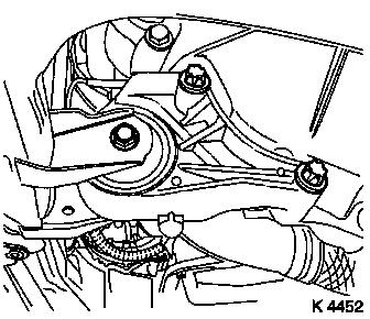
| 43. |
Remove front reaction member
|
|
|
| 44. |
Release shift guide (3)
| • |
Remove retaining clip (2)
|
|
| 45. |
Release rear reaction member (4)
|
|
|
| 47. |
Remove rear of toothed belt cover
|
| 48. |
Lift engine
Note: Observe
manufacturer's instructions
| • |
Carefully raise the engine approx. 40 mm on the timing side
with MKM-883-1
|
|
| 50. |
Remove oil pan
| • |
Prise out 2x closure plugs (1)
|
| • |
Oil pump
| – |
Unscrew 3 bolts (arrows)
|
|
|
|
|
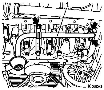
| 51. |
Remove oil intake pipe (1)
| • |
Unscrew 3 bolts (arrows)
|
|
|
|
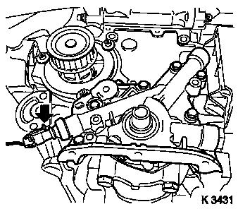
| 52. |
Remove oil pump
| • |
Disconnect oil pressure switch wiring harness plug (arrow)
|
|
| 53. |
Remove crankshaft front seal ring
| • |
Lever out seal ring
Note: Do not damage
sealing surface
|
|
|
|
 Install
| 54. |
Clean sealing surfaces
| • |
Oil pump, cylinder block, oil pan, oil suction pipe, cylinder
head, cylinder head cover
|
|
| 55. |
Inspect components
| • |
Ribbed V-belt, ribbed V-belt tensioner, ribbed V-belt pulley,
toothed belt drive, camshafts, oil pump, oil suction pipe
|
|
| 57. |
Install oil pump
| • |
Insert bolts with locking compound
|
| • |
Connect oil pressure switch wiring harness plug
|
|
| 58. |
Install crankshaft front seal ring
| • |
Coat seal lip with grease
|
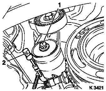
| • |
Attach KM-6010 to crankshaft journal
(1)
|
| • |
Slide seal ring over KM-6010
|
| • |
Pull in crankshaft front seal ring with KM-6010 (4), bolt (2) and crankshaft ribbed V-belt
pulley washer (3)
|
|
| 59. |
Install oil intake pipe
| • |
Insert bolts with locking compound
|
|
|
|
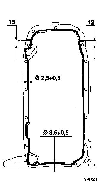
| 60. |
Install oil pan
| • |
Apply sealant
| – |
Complete assembly operations within 10 minutes
|
|
| • |
Screw in bolts
Note: Note tightening
sequence.
|
| • |
At cylinder block
| – |
Tighten 12x bolts 10 Nm
|
|
| • |
Insert 2x closure plugs
|
|
| 62. |
Lower engine
Note: When lowering pay
attention to the shift guide and rear reaction member
|
| 64. |
Fasten rear reaction member
|
| 65. |
Install front reaction member
| • |
Tighten bolted connection 60 Nm
|
|
|
|
| 66. |
Attach KM-6169
| • |
Position KM-6169 on left on front axle body
| – |
Guide pin must be seated in bore in front axle body
|
|
| • |
Attach both right holders on the front axle body
| – |
Guide pin must be seated in bore in front axle body
|
|
|
| 67. |
Install support
| • |
An KM-6169
| – |
Adjust mount for support
|
|
|
| 68. |
Adjust supports
| • |
Transmission side
| – |
Turn spindles until mounts are positioned at guide journals
free of play
|
|
| • |
Engine timing side
| – |
Insert journal of the support in the bore of the cylinder block
free of play
|
|
|
| 69. |
Attach exhaust system
| • |
Connect oxygen sensor (catalytic converter control) cable
harness plug.
|
|
| 70. |
Install rear toothed belt cover
|
| 71. |
Install toothed belt drive gear
| • |
Install crankshaft V-belt pulley bolt
|
|
| 72. |
Install toothed belt tension roller
| • |
Detent lever (1) of toothed belt tension roller must engage in
guide web (2) of oil pump.
|
| • |
Bolt in bolt
Note: Adjust toothed
belt tension before tightening bolt.
|
|
|
|
| 73. |
Install right engine bracket
| • |
Insert bolts with locking compound (red)
|
| • |
Tighten 3x bolts 65 Nm + 45° -
60°
|
|
|
|
| 74. |
Install intake side toothed belt guide roller
Note: The toothed belt
guide roller with the greater diameter is installed at the intake
side.
|
| 75. |
Install exhaust side toothed belt guide roller
|
| 76. |
Install camshaft sprocket on exhaust side
Note: Attach camshaft
sprocket with cylinder recognition to exhaust camshaft.
| • |
Attach KM-6347 , KM-956-1
|
| • |
Tighten bolt 50 Nm + 60° +
15°
Note: 2nd fitter
required
|
| • |
Remove KM-6347 , KM-956-1
|
|
| 77. |
Install camshaft sprocket on the intake side
Note: Attach camshaft
sprocket with cylinder recognition to exhaust camshaft.
| • |
Attach KM-6347 , KM-956-1
|
| • |
Tighten bolt 50 Nm + 60° +
15°
Note: 2nd fitter
required
|
| • |
Remove KM-6347 , KM-956-1
|
|
| 78. |
Fix camshaft sprockets in position.
| • |
Marks must be opposite one another and aligned with the top
edge of the cylinder head (I)
|
| • |
Use KM-852 (II)
| – |
Turn the camshafts at hexagonal section
|
|
|
| 79. |
Lock crankshaft
| • |
Set crankshaft to mark.
| – |
Marks on drive gear toothed belt and rear toothed belt cover
must align (III).
|
|
|
|
|
| 80. |
Inspect components
| • |
Ribbed V-belt, ribbed V-belt tensioner, ribbed V-belt pulleys,
toothed belt drive
|
|
| 81. |
Install toothed belt
Note: Pay attention to
direction of travel and timing marks.
| • |
Position toothed belt
| – |
Tensioned side must be taut.
|
|
|
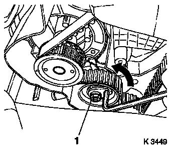
| 82. |
Tension toothed belt
| • |
Tension toothed belt tension roller
| – |
Turn adjusting eccentric in direction of arrow (anticlockwise)
until pointer of the toothed belt tension roller is located just
before left stop
|
|
| • |
Fasten toothed belt tension roller bolt (1)
|
|
|
|
| 84. |
Timing, Check
| • |
Turn crankshaft in direction of engine rotation at the
crankshaft ribbed V-belt pulley bolt (720°)
|
| • |
Set crankshaft to mark.
| – |
Marks on drive gear toothed belt and rear toothed belt cover
must align (III).
|
|
| • |
Use KM-852 (II)
| – |
Marks must be opposite one another and aligned with the top
edge of the cylinder head (I)
|
|
|
|
|
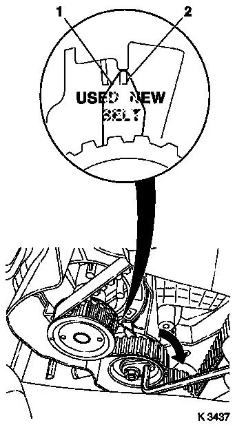
| 86. |
Adjust toothed belt tension
| • |
Release toothed belt tension roller
|
| • |
Turn adjustment eccentric in the direction of the arrow
(clockwise) until pointer (1) of toothed belt tension roller is
aligned with the notch mark NEW (2).
|
| • |
Tighten toothed belt tension roller bolt 20 Nm
|
|
| 87. |
Check toothed belt tension
| • |
Pointer on the toothed belt tension roller and notch mark NEW
must align
|
|
|
|
| 88. |
Install lower part of toothed belt cover
| • |
Clip to rear of toothed belt cover
|
|
| 89. |
Install upper part of toothed belt cover
| • |
Clip to rear toothed belt cover
|
|
| 90. |
Connect camshaft sensor wiring harness plug
| • |
Connect wiring harness plug
|
|
| 91. |
Install right engine damping block
| • |
Fasten engine bracket adapter
| – |
Tighten 2x bolts 60 Nm + 30° -
45°
|
|
| • |
Fasten engine damping block
|
|
| 95. |
Install ribbed V-belt tensioner
| • |
Tension ribbed V-belt tensioner with KM-913-A
|
|
| 96. |
Attach crankshaft ribbed V-belt pulley
| • |
Tighten bolt 95 Nm + 30° +
15°
|
| • |
Insert front closure plug
|
|
| 97. |
Install ribbed V-belt
Note: Observe running
direction and installation position
| • |
Slacken ribbed V-belt tensioner with KM-913-A
|
|
| 98. |
Install ribbed V-belt cover
|
| 99. |
Install right-hand air duct
|
| 101. |
Attach front right wheel
|
| 103. |
Fasten right front wheel.
|
| 104. |
Install air cleaner housing
| • |
Attach engine vent hose
|
| • |
Clip in tank vent valve
|
| • |
Connect 2 wiring harness plugs
|
|
| 105. |
Install engine cover.
| • |
Unscrew oil filler pipe cap
|
| • |
Screw on oil filler pipe cap
|
|
| 107. |
Calibrate steering angle sensor
| • |
Rotate the steering wheel one time from its right-hand to its
left-hand stop
|
|
| 108. |
Program volatile memories
|
|
