|
Remove and install timing case (Z 12 XE, Z 12 XEP,
Z 14 XEP, with air conditioning, LHD)
Note: KM-6394 must be used as of model year 04 instead of
KM-6169-1 .
 Remove Remove
| 2. |
Disconnect battery
Note: On vehicles as of
model year 04 with ESP - the steering angle sensor loses its basic
adjustment each time the battery is disconnected. It must be
recalibrated.
|
| 4. |
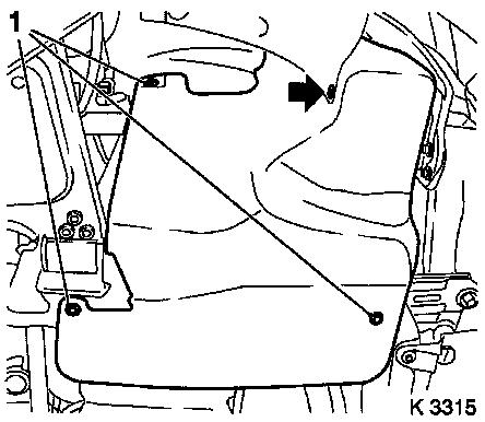
Drain coolant
| • |
Place collecting basin underneath.
|
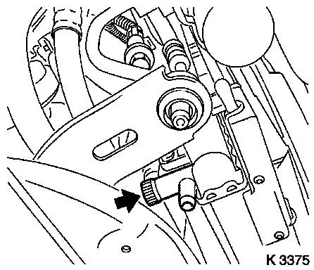
| • |
Open drain bolt (arrow)
|
|
|
|
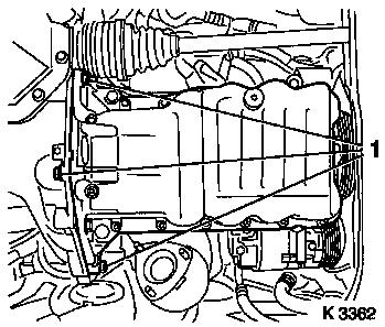
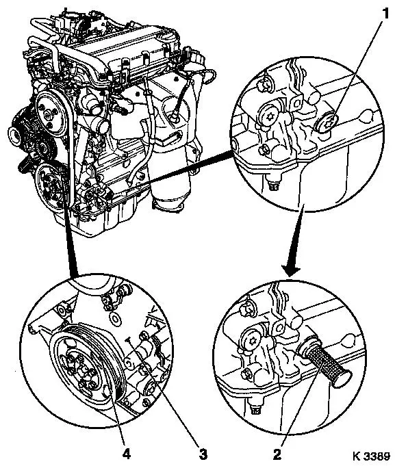
| 6. |
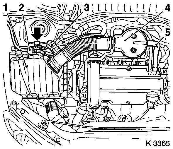
Remove air cleaner housing (1)
| • |
Disconnect 2 wiring harness plugs
| – |
Hot film mass air flow sensor (3), tank vent valve (2)
|
|
| • |
Remove suction pipe (4)
| – |
Detach engine vent hose (5)
|
|
| • |
For Z 12 XEP, Z 14 XEP: detach air intake hose
|
|
|
|
| 7. |
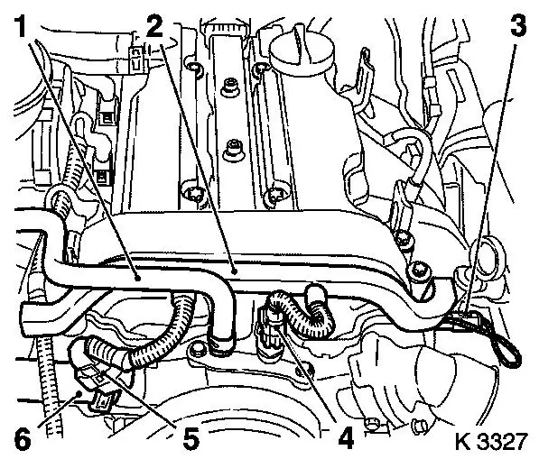
Detach throttle body preheater hose (1)
|
| 8. |
Detach heater supply hose (6) from coolant pump
|
|
|
| 9. |
Remove engine management wiring harness
| • |
Disconnect 3 wiring harness plugs
| – |
oil pressure switch (3), coolant temperature sensor (4) and
camshaft sensor (5)
|
|
| • |
Unclip wiring trough (2)
|
| • |
Set wiring harness to one side
|
|
| 10. |
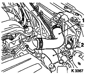
Remove upper radiator hose (1)
|
| 11. |
Detach lower radiator hose (2) from coolant pump
|
| 12. |
Loosen compressor
| • |
Disconnect wiring harness connector.
|
|
|
|
| 13. |
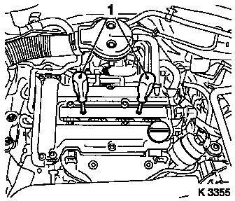
Remove ignition module
| • |
Remove ignition module cover
|
| • |
Disconnect wiring harness connector.
|
| • |
Extract using KM-6009 (1)
Note: Do not tilt
|
|
|
|
| 14. |
Remove cylinder head cover
| • |
Detach engine vent hose
|
|
| 15. |
Detach front right wheel
|
| 17. |
Remove right front wheel
|
| 19. |
Remove ribbed V-belt cover
|
| 20. |
Close coolant drain bolt
|
| 21. |
Drain engine oil
| • |
Place another collecting basin underneath
|
|
|
|
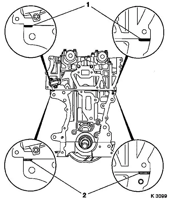
Important: Angular dislocations
of the flexpipe as small as 5 to 10 degrees offset from the
intended installation position can cause damage and subsequent
complete failure of the flexpipe.
|
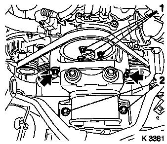
| 22. |
Loosen exhaust system
Note: When removing the
centre muffler, a catalytic converter, an exhaust manifold or
exhaust manifold with catalytic converter, the exhaust system piece
remaining in the vehicle must be secured to prevent it sagging
uncontrollably. The exhaust system piece with the flex pipe inside
it can be fastened to the vehicle underbody with suitable materials
such as wire.
| • |
Detach oxygen sensor (catalytic converter control) wiring
harness plug (1)
|
| • |
Detach 2x damper rings (arrows)
|
| • |
Unbolt front exhaust pipe (2)
|
| • |
Suspend front exhaust pipe from left front axle body
|
|
| 23. |
Install engine oil drain bolt
|
|
|
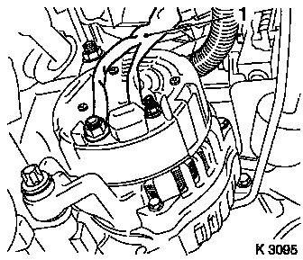
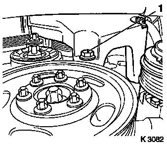
| 24. |
Remove alternator wiring harness (1)
|
|
|
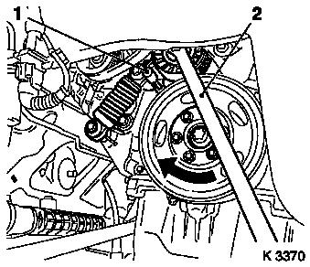
| 25. |
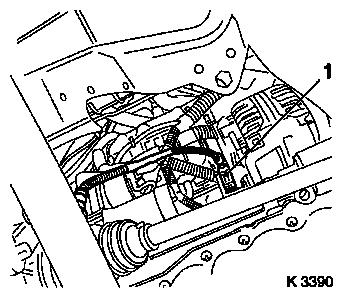
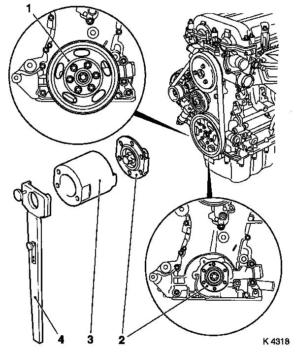
Remove ribbed V-belt
| • |
Tension ribbed V-belt tensioner in direction of arrow with
KM-6131
|
|
|
|
| 26. |
Remove ribbed V-belt tensioner
Note: Ensure that the
ribbed V-belt tensioner is positioned correctly (arrow pointing
upwards). If this is not guaranteed, the ribbed V-belt tensioner
must be bled. At least 5 strokes must be performed
(tensile/pressure load), whereby the load speed should be constant
and the application of load even. Damage to the tensioning element
must be avoided!
| • |
Tension ribbed V-belt tensioner with KM-6131
|
| • |
Release ribbed V-belt tensioner
|
|
|
|
| 27. |
Remove alternator
| • |
Undo 2 screw connections (1)
|
| • |
Remove oxygen sensor (catalytic converter control) bracket
|
|
|
|
| 28. |
Remove oil pan
| • |
Crankshaft bearing bridge
|
|
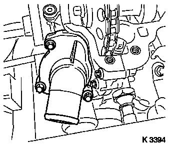
| 29. |
Remove compressor
Note: The air
conditioning system remains closed
|
|
|
| 30. |
Attach KM-6169-2 to transmission
|
|
|
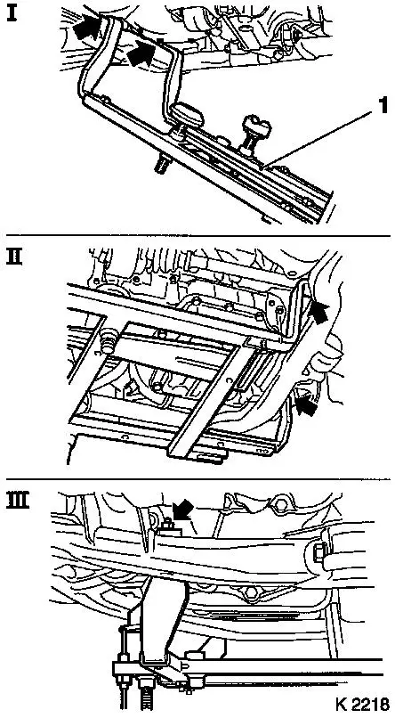
| 31. |
Attach KM-6169 (1)
| • |
Attach KM-6169 to left of front axle
body (arrows, illus. I)
Note: Guide pin must be
seated in bore in front axle body
|
| • |
Attach both right holders on the front axle body (arrows,
Illus. II).
Note: Guide pin must be
seated in bore in front axle body (arrow, Fig. III)
|
|
|
|
|
| 32. |
Install support
| • |
An KM-6169
| – |
Adjust bracket (2) for support
|
|
|
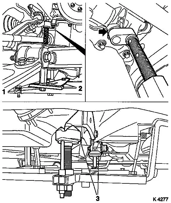
| 33. |
Adjust supports
| • |
Transmission side
| – |
Turn spindles until mounts (3) are positioned at guide journals
free of play
|
|
| • |
Engine timing side
| – |
Insert journal of the support in the bore of the cylinder block
without play (arrow)
|
|
|
|
| 34. |
Loosen right engine bracket
|
|
|
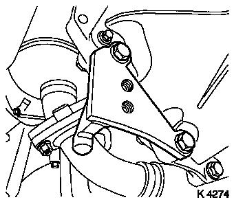
| 38. |
Remove right engine bracket
| • |
Loosen engine damping block
|
| • |
Unscrew 2x bolt (arrows)
|
|
| 39. |
Remove ribbed V-belt
Note: Mark running
direction.
|
| 40. |
Remove coolant pump ribbed V-belt pulley
|
|
|
| 41. |
Detach ribbed V-belt tensioner
|
| 42. |
Detach thermostat housing
|
|
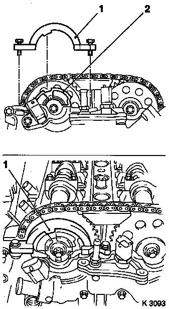
|
|
| 43. |
Set no.1 cylinder to TDC
| • |
Remove closure bolt for crankshaft bearing bridge (1)
|
| • |
Insert KM-952 (2)
Note: Mark on
crankshaft belt pulley (4) must line up with lug (3) on timing
case
| – |
Turn crankshaft uniformly until KM-952 engages
|
|
|
|
|
| 44. |
Insert KM-953 (1)
Note: KM-953 must engage in camshaft groove
|
|
|
| 47. |
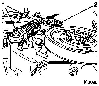
Detach crankshaft ribbed V-belt pulley (1)
| • |
Counterhold at crankshaft hub bolt
|
|
| 48. |
Loosen crankshaft hub bolt
Note: Second person
required
| • |
Attach KM-956-1 KM-956-2 (4)
|
| • |
Counterhold KM-956-1 KM-956-2
|
|
| 49. |
Detach crankshaft hub (2)
Note: Pay attention to
installation position
| • |
Remove with KM-956-1 KM-956-2
|
|
|
|
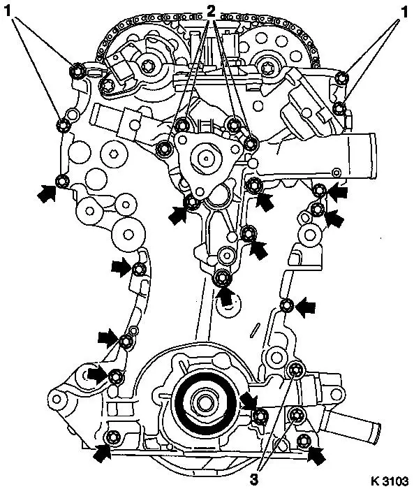
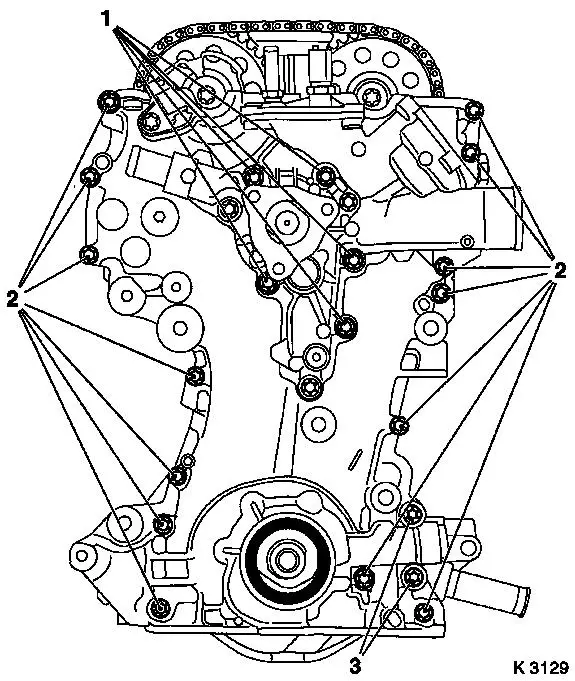
| 50. |
Loosen timing case at bottom
Note: Note dissimilar
bolt lengths
| • |
Unscrew 2 bolts (3) (M10)
|
| • |
Unscrew 14 bolts (M6) (arrows)
|
|
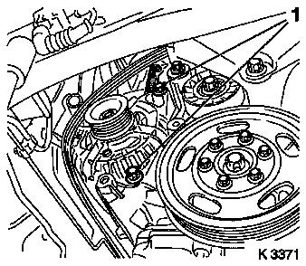
| 52. |
Remove coolant pump
Note: Note guide
bushings during removal
| • |
Place another collecting basin underneath
|
| • |
Unscrew 4 bolts (2)
Note: Note dissimilar
bolt lengths
|
|
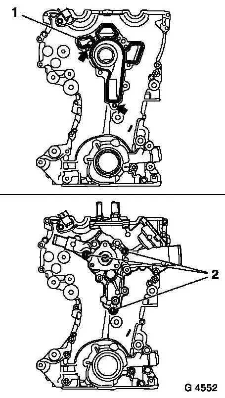
| 53. |
Remove timing case
| • |
Unscrew 4x bolt (1)
Note: Note dissimilar
bolt lengths
|
|
|
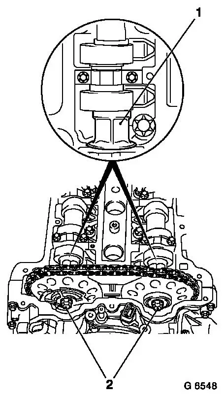
|
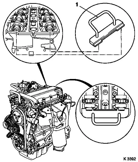
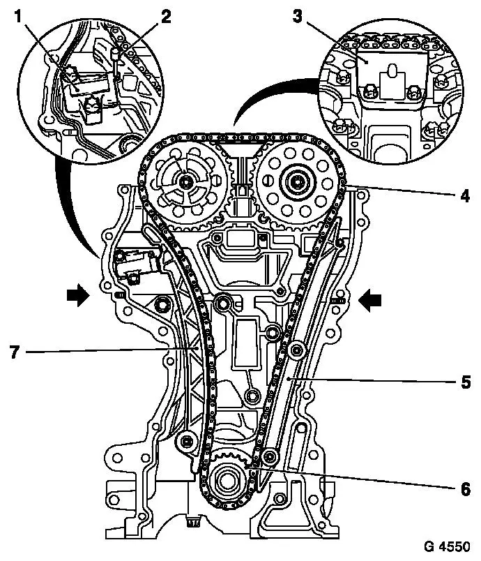
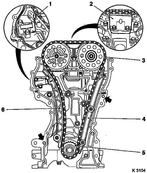
| 54. |
Remove chain drive
| • |
Undo 2 camshaft sprocket bolts
| – |
Counterhold camshafts at hexagonal section
|
|
| • |
Lock chain tensioner (1)
|
| • |
Detach sliding rail (3), guide rail (5), tension rail (7) and
camshaft sprockets
|
| • |
Remove timing chain (4) with drive sprocket (6)
|
| • |
Remove timing case gasket.
|
|
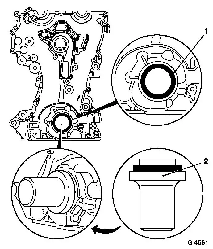
| 55. |
Remove front crankshaft seal ring
| • |
Lever out seal ring
Note: Do not damage
sealing surface
|
|
|
 Install
| 56. |
Clean sealing surfaces
| • |
Timing case, cylinder block, cylinder head, crankshaft bearing
bridge, oil pan, cylinder head cover, coolant pump, thermostat
housing
|
| • |
If present, remove sealing compound from vicinity of cylinder
head gasket
|
|
| 57. |
Inspect components
Note: If cylinder head
is to be checked and overhauled : Remove all outer attaching parts
from cylinder head.
| • |
Chain drive, timing case, cylinder block, cylinder head,
crankshaft bearing bridge, oil pan, cylinder head cover, coolant
pump, thermostat housing
|
|
| 58. |
Note the different versions when replacing components! Be sure
to use the correct part and catalogue number!
- See New Technical Features 2004

- See New Technical Features 2004.5
|
|
| 59. |
Replace crankshaft front seal ring (1)
| • |
Coat sealing lips with silicon grease
|
| • |
Drive in until flush using KM-960
|
|
|
|
| 60. |
Replace timing case gasket
| • |
Apply silicone sealant to joint between cylinder block and
crankshaft bearing bridge
Note: Complete assembly
operations within 10 minutes
|
| • |
Cut off excess elastomer of cylinder head gasket (1) and
replace with a 2 mm thick bead of silicone sealant (2)
Note: If no excess
elastomer is present, the bead of silicone sealant can be applied
directly
|
|
|
|
| 61. |
Attach timing chain
Note: Ensure that guide
sleeves are correctly seated (arrows)
| • |
Attach exhaust camshaft sprocket
|
| • |
Install timing chain (3)
|
| • |
Insert intake camshaft sprocket with phase sensor disc in
timing chain
| – |
Bolt in bolt
Note: It must be
possible to rotate phase sensor disk by hand
|
|
|
|
|
| 62. |
Attach timing chain tension rail (6)
| • |
Tighten bolt 20 Nm
Note: Ensure that
timing chain is correctly seated
|
|
| 63. |
Attach timing chain guide rail (4)
Note: Ensure that
timing chain is correctly seated
|
| 64. |
Attach timing chain sliding rail (2)
|
|
| 66. |
Attach coolant pump
Note: Ensure that guide
sleeves are correctly seated (arrows)
| • |
Attach using short bolts (2)
|
|
|
|
|
| 67. |
Attach timing case.
Note: Note tightening
sequence.
| • |
Tighten 5 bolts (1) (M6) 8 Nm
|
| • |
Tighten 14 bolts (2) (M6) 8 Nm
|
| • |
Tighten 2 bolts (3) (M10) 35 Nm
|
|
| 68. |
Install thermostat housing
|
| 70. |
Remove KM-952
Note: Retaining tools
must not be used for counterholding
|
|
| 71. |
Attach crankshaft hub (1)
Note: Note crankshaft
hub installation position - mark must point upwards
|
| 72. |
Tighten crankshaft hub bolt
Note: Second person
required
| • |
Counterhold with KM-956-1 KM-956-2 (2)
|
| • |
Tighten bolt 150 Nm + 45°
|
| • |
Detach KM-956-1 KM-956-2
|
|
| 73. |
Attach crankshaft ribbed V-belt pulley
| • |
Counterhold at crankshaft hub bolt
|
|
|
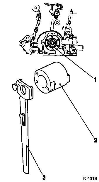
|
| 76. |
Attach KM-954 (1)
| • |
Rotate phase sensor disk (2) until KM-954 can be attached to timing case
|
|
|
|
| 77. |
Fasten camshaft sprockets
Note: First tighten
intake camshaft sprocket bolt
| • |
Tighten 2 bolts (2) 10 Nm
Note: Tightening torque
of 10 Nm is used to secure the camshaft sprockets and the phase
sensor disk
| – |
Counterhold camshafts at hexagonal section (1)
|
|
|
| 78. |
Remove retaining tools
Note: Retaining tools
must not be used for counterholding
| • |
KM-952 , KM-953 , KM-954
|
|
| 79. |
Fasten camshaft sprockets
Note: Second person
required
| • |
Tighten bolts 50 Nm + 60°
Note: First tighten
intake camshaft sprocket bolt
| – |
Counterhold camshafts at hexagonal section
|
|
|
|
|
| 81. |
Remove retaining tools
| • |
KM-952 , KM-953 , KM-954
|
|
| 82. |
Attach ribbed V-belt tensioner
| • |
Tighten bolt (M10) 55 Nm
|
|
| 83. |
Attach coolant pump ribbed V-belt pulley
|
| 84. |
Install ribbed V-belt
Note: Note running
direction
|
| 85. |
Install right engine bracket
| • |
Tighten 2 upper bolts 60 Nm
|
| • |
Fasten engine damping block
|
|
| 87. |
Fasten right engine bracket
| • |
Tighten lower bolt 60 Nm
|
|
| 92. |
Attach closure bolt of crankshaft bearing bridge
|
| 93. |
Attach oil pan
Note: Note tightening
sequence.
| • |
On crankshaft bearing bridge
|
|
| 94. |
Install alternator
| • |
Tighten 2 bolted connections 35
Nm
|
|
| 95. |
Screw on alternator wiring harness
|
| 96. |
Fasten compressor
| • |
Tighten 2 lower bolts 20 Nm
|
|
| 97. |
Install ribbed V-belt tensioner
| • |
Tighten bolt (M8) 20 Nm
|
| • |
Tighten bolt (M10) 55 Nm
|
| • |
Tension ribbed V-belt tensioner in direction of arrow with
KM-6131
|
| • |
Release ribbed V-belt tensioner
|
|
| 98. |
Install ribbed V-belt
Note: Note running
direction
| • |
Tension ribbed V-belt tensioner with KM-6131
|
| • |
Release ribbed V-belt tensioner
|
|
| 99. |
Attach exhaust system
| • |
Connect oxygen sensor (catalytic converter control) wiring
harness plug.
|
|
| 100. |
Install ribbed V-belt cover
Note: In "ECO" model
variant install lower engine compartment cover, see operation
"J481500 Removing and installing lower engine compartment cover
(ECO)" in group "A"
|
| 102. |
Attach front right wheel
|
| 104. |
Fasten right front wheel
|
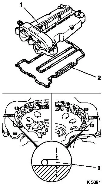
| 105. |
Attach cylinder head cover (1)
Note: Complete assembly
operations within 10 minutes
| • |
Apply sealant (dimension I = 2 mm)
|
| • |
Attach engine vent hose
|
|
| 106. |
Install ignition module
| • |
Connect wiring harness plug
|
| • |
Attach ignition module cover
|
|
| 107. |
Connect wiring harness for engine management
| • |
Connect 3 wiring harness plugs
|
|
| 108. |
Fasten compressor
| • |
Tighten upper bolt ( 20 Nm
|
| • |
Connect wiring harness plug
|
|
|
|
| 109. |
Connect lower radiator hose
|
| 110. |
Install upper radiator hose
|
| 111. |
Attach heater supply hose
|
| 112. |
Install air cleaner housing
| • |
For Z 12 XEP, Z 14 XEP: attach air intake hose
|
| • |
Attach engine vent hose
|
| • |
Connect 2 wiring harness plugs
|
|
| 114. |
Calibrate steering angle sensor
| • |
Rotate the steering wheel one time from its right-hand to its
left-hand stop
|
|
| 115. |
Top up and bleed cooling system – see operation "Cooling
System, Top up and Bleed"
|
| 116. |
Top up engine oil
| • |
Observe specified engine oil quantity
|
| • |
Start engine and allow to run until oil pressure telltale
extinguishes.
|
| • |
Check engine oil level, if necessary correct.
|
|
| 117. |
Program volatile memory
|
|
