|
Adjust timing (Z 12 XE, Z 12 XEP, Z 14 XEP, with
air conditioning, LHD)
 Remove Remove
| 2. |
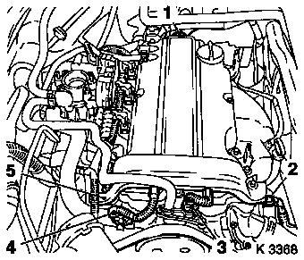
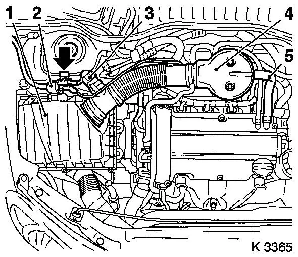
Disconnect 4 cable management wiring harness plugs
| • |
Oil pressure switch (2), coolant temperature sensor (3),
camshaft sensor (4) and ignition module (1)
|
| • |
Unclip wiring trough (5)
|
| • |
Set wiring harness to one side
|
|
|
|
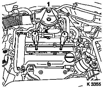
| 3. |
Remove ignition module
| • |
Remove ignition module cover
|
| • |
Extract using KM-6009 (1)
Note: Do not tilt
|
|
| 4. |
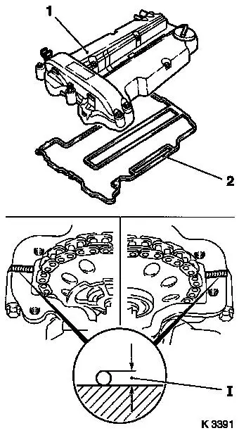
Remove cylinder head cover
| • |
Detach 2 engine vent hoses
|
|
|
|
| 6. |
Remove ribbed V-belt cover
|
|

|
|
| 7. |
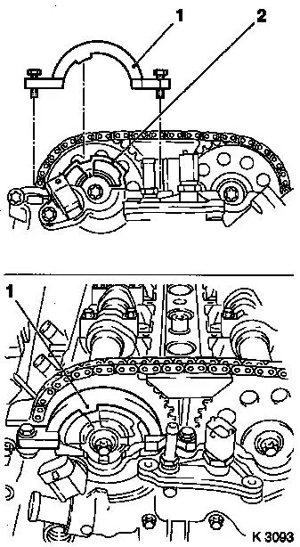
Remove closure bolt for crankshaft bearing bridge (1)
|
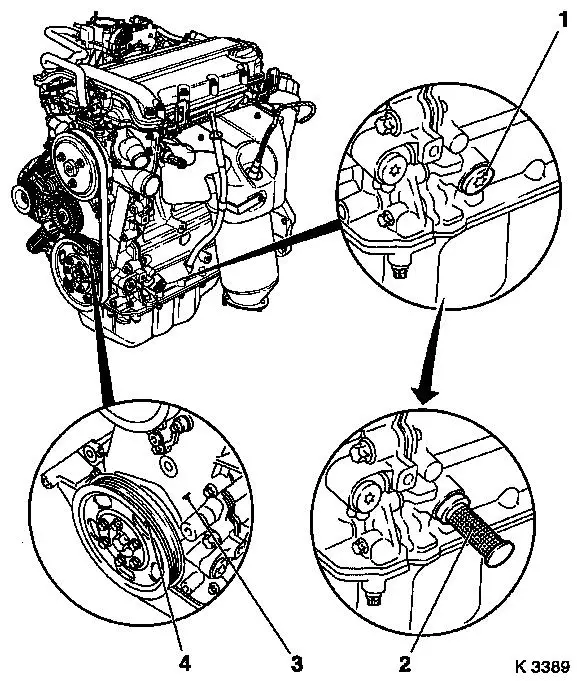
| 9. |
Set no.1 cylinder to TDC
| • |
Insert KM-952 (2)
| – |
Turn crankshaft uniformly until KM-952 engages
Note: Mark on
crankshaft belt pulley (4) must line up with lug (3) on timing
case
|
|
|
|
|
| 10. |
Insert KM-953 (1)
| • |
KM-953 must engage in camshaft
groove
Note: If the KM-953 cannot be inserted, a basic timing
adjustment must be made
|
|
|
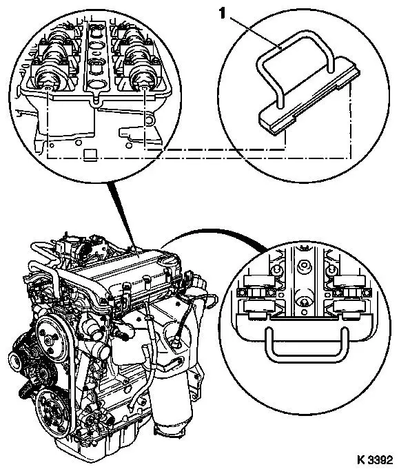
| 11. |
Attach KM-954 (1)
| • |
Position on phase sensor disc (2)
Note: KM-954 must engage in groove in phase sensor disk
|
|
| 12. |
Remove retaining tools
Note: Retaining tools
must not be used for counterholding
| • |
KM-952 , KM-953 , KM-954
|
|
|
|
| 13. |
Remove air cleaner housing (1)
| • |
Disconnect 2 wiring harness plugs
| – |
Hot film mass air flow sensor (3), tank vent valve (2)
|
|
| • |
Remove suction pipe (4)
|
| • |
For Z 12 XEP, Z 14 XEP: detach air intake hose
|
|
|
|
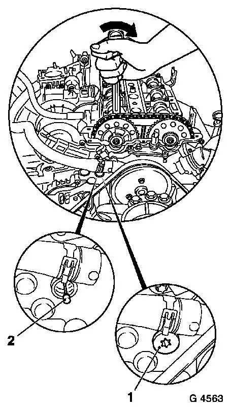
| 14. |
Lock chain tensioner
| • |
Remove closure bolt (1)
|
| • |
Load intake camshaft in direction of arrow via hexagonal
section using an open-ended spanner
|
|
|
|
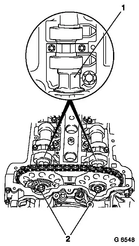
| 15. |
Release camshaft sprockets
| • |
Loosen 2 bolts (2)
| – |
Counterhold camshafts at hexagonal section (1)
|
|
|
| 16. |
Replace camshaft sprocket bolts
|
|
|
|
| 18. |
Adjust camshafts
| • |
Insert KM-953 (1)
| – |
Turn the camshafts at hexagonal section
|
|
|
|
| 19. |
Attach KM-954 (1)
| • |
Position on phase sensor disc (2)
Note: KM-954 must engage in groove in phase sensor disk
|
|
|
|
| 20. |
Remove KM-955-1
| • |
Tighten chain tensioner closure bolt 50
Nm
|
|
| 21. |
Fasten camshaft sprockets
Note: Tightening torque
of 10 Nm is used to secure the camshaft sprockets and the phase
sensor disk
| • |
Tighten 2 bolts (2) 10 Nm
Note: First tighten
intake camshaft sprocket bolt
| – |
Counterhold camshafts at hexagonal section (1)
|
|
|
| 22. |
Remove retaining tools
Note: Retaining tools
must not be used for counterholding
| • |
KM-952 , KM-953 , KM-954
|
|
| 23. |
Fasten camshaft sprockets
Note: Second person
required
| • |
Tighten 2 bolts 50 Nm + 60°
Note: First tighten
intake camshaft sprocket bolt
| – |
Counterhold camshafts at hexagonal section
|
|
|
|
|
| 25. |
Remove retaining tools
| • |
KM-952 , KM-953 , KM-954
|
|
 Install
| 27. |
Attach closure bolt of crankshaft bearing bridge
|
| 28. |
Install ribbed V-belt cover
|
| 30. |
Clean sealing surfaces
| • |
Cylinder head, cylinder head cover
|
|
| 31. |
Attach cylinder head cover (1)
| • |
Renew gasket (2) and seal rings
|
| • |
Apply sealant (dimension I = 2 mm)
Note: Complete assembly
operations within 10 minutes
|
|
| 32. |
Attach 2 engine vent hoses
|
|
|
| 33. |
Attach ignition module
|
| 34. |
Install engine management wiring harness
| • |
Connect 4 wiring harness plugs
|
|
| 35. |
Install air cleaner housing
| • |
For Z 12 XEP, Z 14 XEP: attach air intake hose
|
| • |
Attach engine vent hose
|
| • |
Attach engine vent hose
|
| • |
Connect 2 wiring harness plugs
|
|
|
