Alternator, Overhaul
Remove and disassemble alternator, see corresponding
operation.
Cleaning petrol can be used as a cleaning agent.
Electrical windings should only be brought into contact with
the cleaning agent briefly. Cleaned parts should be immediately blown with
compressed air.
Wash out ball bearing. Replace defective ball bearings.
Clean housing parts.
Clean stator and claw pole rotor.
|
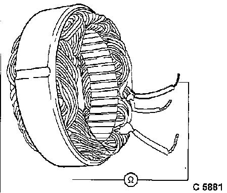
Check all phases of stator winding for short circuit to
ground using ohmmeter.
Ohmmeter must indicate infinity.
Replace stator with short circuit to ground.
|

|
|
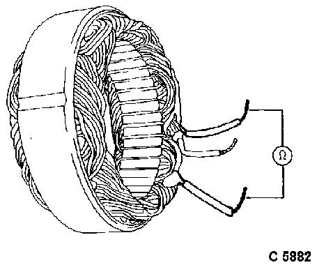
Check all phases of stator winding for short-circuited windings
using ohmmeter (ohmic resistance).
Resistance between two phases is measured.
Hold probes alternately on ends of windings.
Test value: approx. 0.1 W
at 20 °C/68 °F
Replace stator with short-circuited winding.
|
|
|
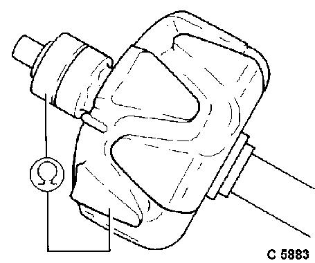
Check rotor winding and slip rings for short circuit to
ground using ohmmeter.
Ohmmeter should indicate a high insulation value.
Replace rotor with short circuit to ground.
|
|
|
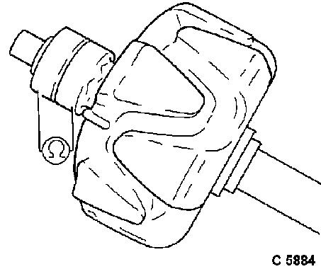
Check rotor winding for short-circuited winding using
ohmmeter (ohmic resistance).
Resistance of excitation winding from slip ring to slip ring is
measured.
Test value: approx. 3.6 W at 20 °C/68 °F
Replace rotor with short circuit.
|
|
|
Clean and polish slip rings on a lathe with fine emery paper
(grain 500 - 600).
Slip rings which are uneven can be turned down to
30 mm/1.18 in.
When doing this, only remove as much material as is
necessary to even out the worn sections. Afterwards, slip rings should again
be polished and blown dry.
|
|
|
Diodes, Check
Circuit diagram of an electronically-regulated alternator
1 Rectifier diodes
2 Excitation diodes
3 Stator winding
4 Excitation winding
5 Installed electronic voltage
regulator
6 Battery
7 Ignition lock
8 Charge telltale
9 Charge telltale relay
|

|
The diodes should be tested for continuity, interruption,
short circuit and blocking action.
The test result only permits qualitative assessments of the
effectiveness of the diode or the condition of the barrier layer. If a precise
check of the diodes is required, a diode tester should be used and the
instructions that go with it carefully observed.
If any of the diodes prove faulty, the whole set should be
replaced.
When checking diodes using a test lamp, only use equipment up
to 24 volts DC.
|
Negative Diodes (1), Check Individually
Hold positive probe (2) on diode housing and other probe (3)
on diode connection.
Test lamp must light up.
Exchange probes and check again.
Test lamp must not light up.
Negative diodes show continuity from housing to connection
and block in the reverse direction.
If any diode is faulty, replace diode plate completely.
|

|
|
Positive Diodes (1), Check Individually
Hold positive probe (2) on diode connection and other probe
(3) on diode housing.
Test lamp must light up.
Exchange probes and check again.
Test lamp must not light up.
Positive diodes show continuity from connection to housing
and 2 block in the reverse direction.
If any diode is faulty, replace diode plate completely.
|

|
|
Excitation Diodes (1), Check Individually
Hold positive probe (2) on long diode connection and other
probe (3) on short diode connection.
Test lamp must light up.
Exchange probes and check again.
Test lamp must not light up.
Excitation diodes show continuity from long to short diode
connection and block in the reverse direction.
If any diode is faulty, replace diode plate completely.
|

|
|
Carbon Brushes, Check
When exchanging carbon brushes, the complete carbon brush
plate must be replaced.
For this, see operation "Alternator, Disassemble and
Assemble".
Replace carbon brushes if worn down to dimension "
1 " = 14 mm/0.55 in.
Check new brushes for ease of run in the brush holders.
Brush length New carbon brushes: 20 mm/0.79 in.
Used carbon brushes
min.: 14 mm/
0.55
in.
|

|
