|
Hydraulic Modulator, Remove and Install or Replace
(ABS 2 SH/TC)
|
Vehicles with Petrol Engines
 Remove Remove
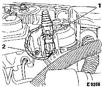
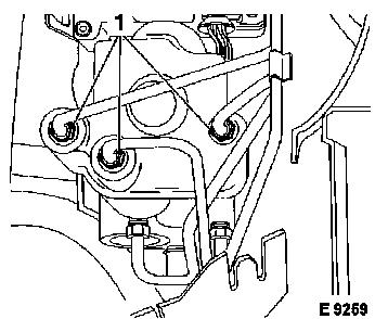
Disconnect battery, disconnect bonnet contact switch (1). Remove
fastening bolt (2) from power steering fluid reservoir bracket and
lay fluid reservoir to one side
|
|
|
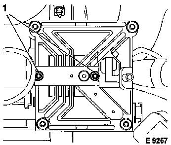
Remove ABS/TC control unit – see operation "ABS/TC Control
Unit, Remove and Install or Replace (ABS 2 SH/TC)". Remove
fastening bolts (1). Remove bracket for ABS/TC control unit.
|
|
|
Vehicles with 4 cylinder engine:
Remove
Unscrew brake lines (1) from hydraulic modulator.
Caution
Brake fluid escapes – collect and close off openings.
|
|
|
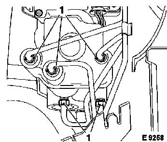
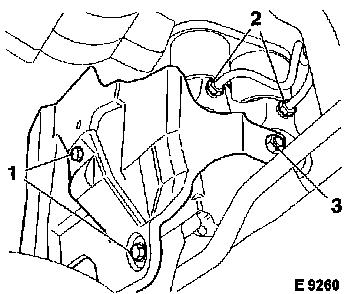
Remove
Remove fastening bolts (1) and fastening nut (2). Remove
hydraulic modulator heat shield
|
|
Vehicles with V6 engine:
|
Remove
Unscrew brake lines (1) from hydraulic modulator.
Caution
Brake fluid escapes – collect and close off openings.
|
|
Remove
|
Raise vehicle. Unscrew engine compartment cover. Unscrew
hydraulic modulator heat shield (1 + 3). Unscrew brake lines (2)
from hydraulic modulator. Lower vehicle.
Caution
Brake fluid escapes – collect and close off openings.
|
|
All Vehicles with Petrol Engine:
|
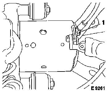
Remove
Connect ground lead (1) to rear of hydraulic modulator.
|
|
|
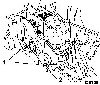
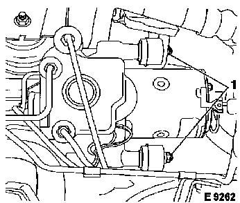
Remove fastening nuts (1) from guide pins. Press brake lines
slightly to one side. Remove hydraulic modulator from rubber
dampers forwards and upwards.
|
|
|
 Install
Insert guide pins of hydraulic modulator in rubber dampers and
fasten with fastening nuts (1) – tightening torque 8 Nm / 6
lbf. ft.
Attach brake lines to hydraulic modulator – tightening
torque 16 Nm / 12 lbf. ft.
|
|
|
Connect ground lead (1) to rear of hydraulic modulator.
|
|
Vehicles with V6 engine:
|
Torque
|
Raise vehicle.
|
|
Brake lines (2) to hydraulic modulator – 16 Nm / 12 lbf.
ft.
|
|
Hydraulic modulator heat shield (1 + 3) – 8 Nm / 6 lbf.
ft.
|
Install
Install engine compartment cover. Lower vehicle.
Vehicles with 4 cylinder engine:
Torque
|
Brake lines to hydraulic modulator – 16 Nm / 12 lbf.
ft.
|
|
Hydraulic modulator to bracket – 8 Nm / 6 lbf. ft.
|
|
Hydraulic modulator heat shield (1 + 3) – 8 Nm / 6 lbf.
ft.
|
|
|
All Vehicles with Petrol Engine:
|
Install
Insert bracket for ABS/TC control unit and screw in fastening
bolts (1). Install ABS/TC control unit.
|
|
|
Screw in fastening bolt (2) for power steering fluid reservoir
bracket. Insert bonnet contact switch (1). Connect battery.
 Inspect
Bleed brake system and check for leaks – see operation
"Brake System, Bleed" and "Brake System, Check for Leaks".
|
|
Vehicles with Diesel Engines:
|
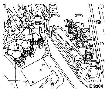
Remove
battery and cover for control unit box. Twist ring to unlock
wiring harness plugs (1) and remove (mark allocation). Remove
engine control unit. Remove wiring harnesses leading to engine with
relays and socket and lay to one side (e.g. tape to valve
cover).
|
|
|
Disconnect bonnet contact switch (1). Remove fastening bolt (2)
from power steering fluid reservoir bracket and lay fluid reservoir
to one side.
|
|
|
Remove ABS/TC control unit – see operation "ABS/TC Control
Unit, Remove and Install or Replace (ABS 2 SH/TC)". Remove
fastening bolts (1). Remove bracket for ABS/TC control unit.
|
|
|
Unscrew brake lines (1) from hydraulic modulator.
Caution
Brake fluid escapes – collect and close off openings.
|
|
|
Remove
Raise vehicle. Unscrew engine compartment cover. Remove heat
shield (1 + 3). Unscrew brake lines (2) from hydraulic
modulator.
Caution
Brake fluid escapes – collect and close off openings.
|
|
|
Remove
Lower vehicle. Disconnect ground lead (1) from rear of hydraulic
modulator.
|
|
|
Remove fastening nut (1) from guide pin. Press brake lines
slightly to one side. Remove hydraulic modulator from rubber
dampers forwards and upwards.
Install
Insert guide bolts of hydraulic modulator in damper blocks.
Torque
Hydraulic modulator to bracket – 8 Nm / 6 lbf. ft.
|
|
|
Install
Connect ground lead (1) to rear of hydraulic modulator.
|
|
|
Torque
|
Raise vehicle.
|
|
Brake lines (2) to hydraulic modulator – 16 Nm / 12 lbf.
ft.
|
|
Heat shield to bracket (1 + 3) – 8 Nm / 6 lbf. ft
|
|
Install engine compartment cover.
|
|
|
Lower vehicle.
|
Torque
Brake lines (1) to hydraulic modulator – 16 Nm / 12 lbf.
ft.
|
|
|
Install
Insert fastening bolts (1) for ABS/TC control unit bracket.
Install ABS/TC control unit.
|
|
|
Screw in fastening bolt (2) for power steering fluid reservoir
bracket. Insert bonnet contact switch (1). Insert wiring harnesses
leading to engine with relays and socket.
Install engine control unit. Connect wiring harness plug (1)
(note allocation). Push on cover for control unit box. Install
battery.
|
|
|
Inspect
Bleed brake system and check for leaks – see operation
"Brake System, Bleed" and "Brake System, Check for Leaks".
|
|
|
