|
Brake Servo, Remove and Install or Replace
|
 Remove Remove
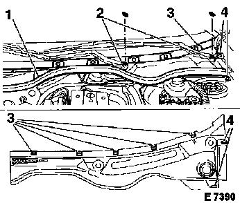
Remove rubber seal (1) and both windscreen wiper arms (2).
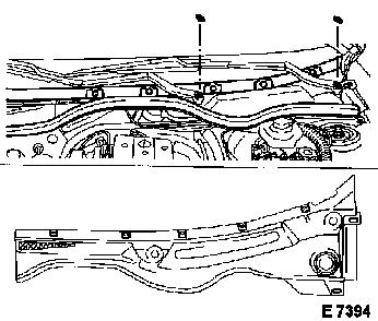
Detach screen trim strip for windscreen at bottom edge. Release
clips (3) for water deflector and remove fastening bolts (4).
Remove water deflector. Detach water deflector bracket from screen
frame. Detach vacuum hose from brake servo.
For vehicles with manual transmission: Siphon off as much brake
fluid as possible from brake fluid reservoir. Detach feed line for
clutch master cylinder from brake fluid reservoir and seal.
|
|
Vehicles with LHD: Remove brake master cylinder – see
operation "Brake Master Cylinder, Remove and Install or
Replace".
Vehicles with diesel engine and RHD: Remove fuel filter or fuel
filter housing, respectively – see operation "Fuel Filter,
Replace" in group "L". Detach fuel filter bracket from spring strut
dome.
For Y 25 DT: Remove fuel filter – see operation "Fuel
Filter, Replace" in group "L". Detach fuel filter bracket from
spring strut dome. Remove fuel pre-heater valve – Disconnect
fuel lines at quick disconnect fittings using KM-796-A and remove
with fuel pre-heater valve.
For RHD vehicles: Disconnect wiring harness plug from brake
fluid level sensor. Detach brake master cylinder from brake servo.
Release brake lines from clips on bulkhead and carefully pull brake
master cylinder slightly forwards – brake system remains
closed.
|
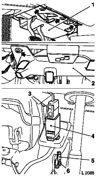
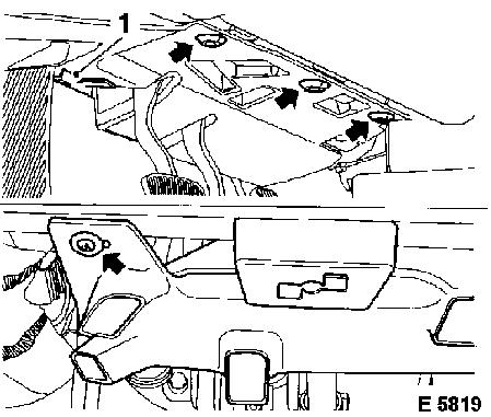
Remove footwell panelling (1) and heating and ventilation ducts
(2).
Detach brake pedal spring from brake pedal. Detach wiring
harness plug (3) from brake light switch (4).
Remove brake light switch – see operation "Brake Light
Switch, Remove and Install or Replace". Pull retaining clip (5)
from pin (6). Press pin (6) out of fork.
Detach fastening nuts from pedal support on bulkhead. Remove
brake servo.
|
|
|
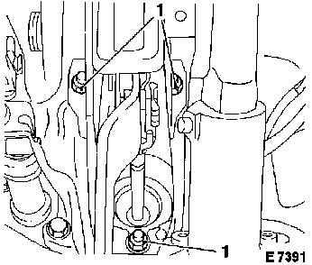
For replacement of brake servo:
 Disassemble
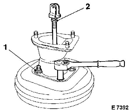
Detach support – fastening nuts (1, according to version 2
or 4 off). Release lock nut (2) and detach from piston rod with
fork. Remove old gasket.
|
|
 Assemble
|
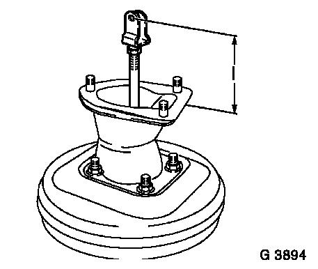
Attach support with new gasket – tightening torque 21 Nm /
15.5 lbf. ft. Attach lock nut and fork to piston rod. Set piston
rod with fork to dimension (I) 106 + 0.5 mm and secure with lock
nut – tightening torque 21 Nm / 15.5 lbf. ft.
|
|
 Install
|
Align pedal support. Attach brake servo to bulkhead panel using
new gasket and new fastening nuts (1) – tightening torque 20
Nm / 15 lbf. ft.
Insert pin through fork and secure with retaining clip. Attach
brake pedal spring. Install brake light switch – see
operation "Brake Light Switch, Remove and Install or Replace".
|
|
|
Install heating and ventilation duct. Push footwell panelling
into guide (1) and fasten.
|
|
|
Vehicles with LHD: Install brake master cylinder – see
operation "Brake master cylinder, Remove and Install or
Replace".
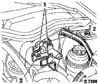
For RHD vehicles: Attach brake master cylinder to brake servo
with new fastening nuts (2) – tightening torque 22 Nm / 16
lbf. ft. Insert brake lines (1) into clips on bulkhead. Connect
wiring harness plug to brake fluid level sensor.
|
|
Vehicles with RHD and diesel engine: Attach fuel filter bracket
or fuel filter housing to spring strut dome – tightening
torque 20 Nm / 15 lbf. ft. Install fuel filter – see
operation "Fuel Filter, Replace" in group "L".
For vehicles with manual transmission: Attach feed line for
clutch master cylinder to brake fluid reservoir. Top up brake fluid
– see operation "Hydraulic Clutch Actuator, Bleed" in group
"K".
|
For Y 25 DT: Install fuel pre-heater valve with fuel lines
– connect fuel lines at quick disconnect fittings using
KM-796-A. Attach fuel filter bracket to spring strut dome –
tightening torque 20 Nm / 15 lbf. ft. Install fuel filter –
see operation "Fuel Filter, Replace" in group "L".
Insert vacuum hose in brake servo. Install water deflector
bracket and water deflector. Fasten rubber seal to water deflector.
Attach windscreen wiper arms – see operation "Windscreen
Wiper Arms, Basic Adjustment" in group "N".
Vehicles with LHD: Bleed brake system and check for leaks
– see operation "Brake System, Bleed" and "Brake System,
Check for Leaks".
|
|
|
