|
Pressure Loss, Check
|
Engine must be at operating temperature (oil temperature >=
80 °C).
 Remove Remove
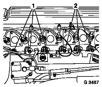
Remove injection lines – see operation "Injection Lines,
Remove and Install".
Remove sheathed glow plugs (1 and 2) – see operation
"Sheathed glow plugs, remove and install".
Version with AC: Remove visco-fan – see operation
"Visco-fan, Remove and Install".
1. Adjust cylinder to "TDC" – see operation "Timing,
Check".
|
|
 Inspect
|
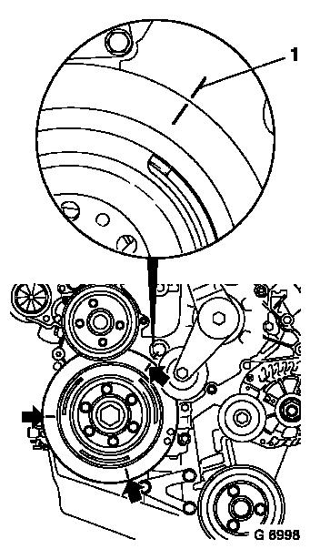
Position guide mark (1) at suitable point on timing case. Guide
mark "1st Cylinder TDC" on torsional vibration damper and guide
mark on timing case must align.
Make guide markings (arrows) every 120° on torsional
vibration damper.
Remove
Remove oil filler opening cap, coolant compensation tank cap and
dipstick.
Caution
The crankshaft is not permitted to rotate during the test
procedure. In order to avoid this, engage 1st gear or selector
lever position "P" and apply parking brake.
|
|
 Install
|
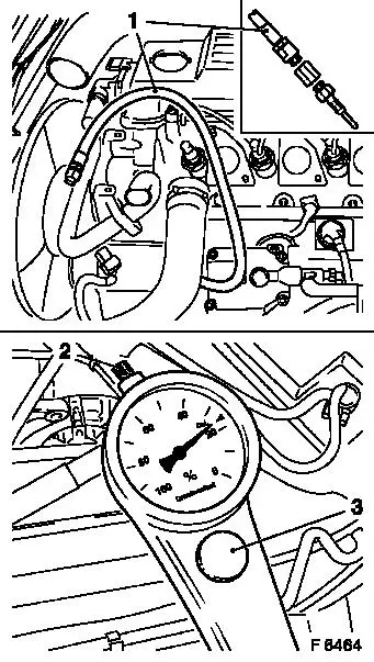
Screw Adapter KM-488 with Connection Piece KM-533-B and
connection hose (1) in threaded bore of sheathed glow plugs –
tightening torque 22 Nm / 16 lbf. ft.
Connect pressure loss tester to a compressed air system and
connect test nozzle (2). Calibrate the compressed air tester by
turning the knurled thumb screw (3). Connect test hose to
connecting piece.
Inspect
Max. pressure difference between individual cylinders 10%. Max.
cylinder pressure loss should not exceed 25%
For the following components, note any escaping air in order to
localise damage: intake ducts, exhaust, coolant compensation tank,
dipstick guide tube and sheathed glow plug threaded bores.
|
|
Inspect
|
Check pressure loss at cylinders 2. to 6. accordingly. Turn
crank shaft in accordance with guide markings (arrows) on torsion
vibration damper. Guide markings must correspond with guide marking
(1) on timing case. Injection order: 1-5-3-6-2-4.
Remove
Remove Adapter KM-488 and Connection Piece KM-533-B. Uncouple
pressure loss tester from compressed air system.
|
|
Install
Install oil filler opening closure cap, coolant compensation
tank closure cap and oil dipstick.
Install sheathed glow plugs – see operation "Sheathed glow
plugs, remove and install".
Install injection lines – see operation "Injection Lines,
Remove and Install".
Version with AC: Install visco-fan – see operation
"Visco-fan, Remove and Install".
|
