|
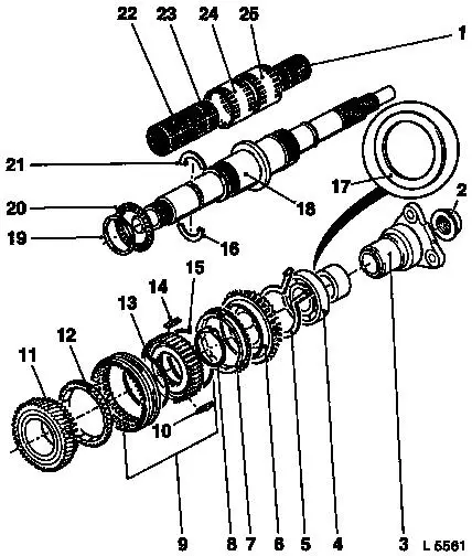
Main Shaft, Disassemble and Assemble (R 25/R 28/R
30)
Illustration
|
1
|
Needle bearing, 5th gear
|
|
2
|
Main shaft fastening nut
|
|
3
|
Main drive clutch assembly
|
|
4
|
Main shaft ball bearing
|
|
5
|
Retaining ring
|
|
6
|
Gear wheel, 5th gear
|
|
7
|
Synchroniser ring
|
|
8
|
Retaining ring
|
|
9
|
5th gear synchromesh body assembly
|
|
10
|
Sliding block
|
|
11
|
Gear wheel, reverse gear
|
|
12
|
Synchroniser ring
|
|
13
|
Spring
|
|
14
|
Sliding block
|
|
15
|
Spring
|
|
16
|
Thrust washer
|
|
17
|
Supporting disk (all R 30 and R 25 / R 28 as of MY 2001)
|
|
|
|
18
|
Main shaft
|
|
19
|
Retaining ring
|
|
20
|
Axial bearing, 1st gear
|
|
21
|
Thrust washer
|
|
22
|
3rd gear needle bearing
|
|
23
|
2nd gear needle bearing
|
|
24
|
1st gear needle bearing
|
|
25
|
Reverse gear needle bearing
|
|
|
|
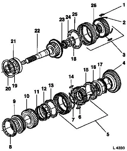
1
|
Sliding block
|
|
2
|
Spring
|
|
3
|
3rd/4th gear synchromesh body assembly
|
|
4
|
1st speed gear
|
|
5
|
1st/2nd gear synchromesh body assembly
|
|
6
|
Sliding block
|
|
7
|
Spring
|
|
8
|
Synchroniser ring
|
|
9
|
3rd speed gear
|
|
10
|
Gear wheel, 5th gear
|
|
11
|
Inner synchroniser ring
|
|
12
|
Intermediate ring
|
|
13
|
Outer synchroniser ring
|
|
14
|
Retaining ring
|
|
15
|
Inner synchroniser ring
|
|
16
|
Intermediate ring
|
|
17
|
Outer synchroniser ring
|
|
18
|
Retaining ring
|
|
|
|
19
|
Retaining ring (large)
|
|
20
|
Retaining ring (small)
|
|
21
|
Ball bearing
|
|
22
|
Drive shaft
|
|
23
|
Needle bearing
|
|
24
|
Gasket
|
|
25
|
Synchroniser ring
|
|
26
|
Spring
|
|
|
 Remove Remove
|
Disassemble transmission – see operation "Transmission,
Disassemble and Assemble".
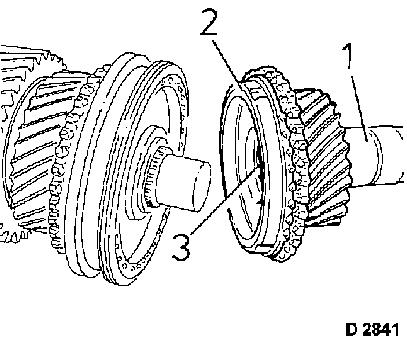
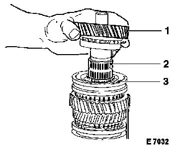
Auxiliary shaft gear cluster from main shaft.
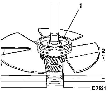
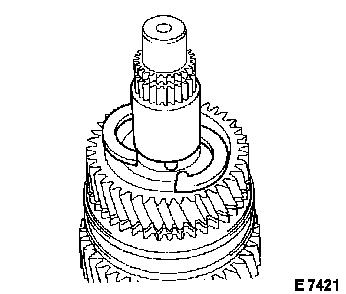
Main drive gear (1) with synchroniser ring of 4th gear (2) and
needle roller bearing (3) from main shaft.
|
|
|
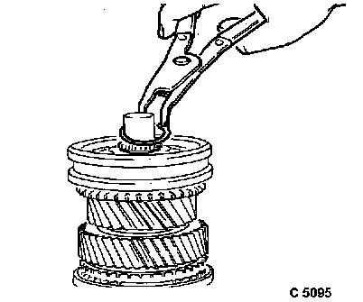
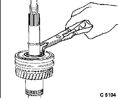
Clamp main shaft in vice – use protective jaws, drive side
of main shaft (without thread attachment) faces upwards.
Retaining ring from main shaft, retaining ring pliers.
|
|
|
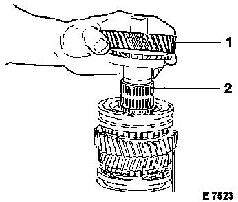
Press 3rd/4th synchromesh body (1), synchroniser ring, 3rd gear
(2) and needle roller bearing from main shaft, KM-307-B. Push
KM-307-B under 3rd gear.
Press off main shaft.
|
|
|
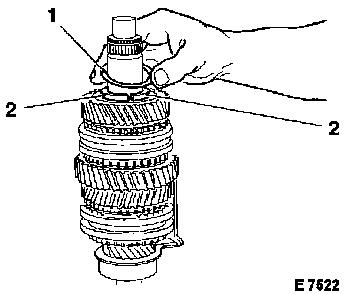
Clamp main shaft in vice with drive side upwards.
Retaining ring (1) and both thrust washer halves (2) from main
shaft.
|
|
|
2nd gear (1) with 3 cone synchromesh unit from main shaft,
needle roller bearing (2) from main shaft.
|
|
|
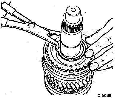
Retaining ring for 1st/2nd synchromesh body from main shaft
using retaining ring pliers.
|
|
|
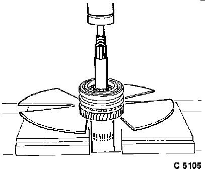
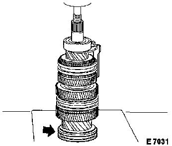
Press off synchromesh body, 3 cone synchromesh unit, 1st gear by
placing 1st gear on 2 flat irons.
|
|
|
Ball bearing of main shaft – KM-307-B. Push KM-307-B under
bearing as far as possible and press main shaft off bearing.
Caution
Align retaining ring to bearing outer ring and attach while
pressing off.
|
|
Remove
|
Clamp main shaft in vice with drive side upwards.
5th gear from main shaft.
|
|
|
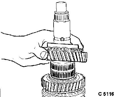
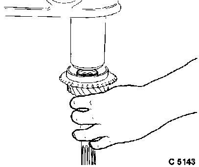
Slotted needle roller bearing for 5th gear from main shaft,
unhook needle roller bearing and spread carefully.
|
|
|
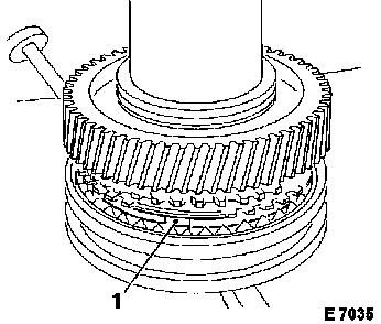
Retaining ring for 5th/reverse synchromesh body from main
shaft.
Press off 5th/reverse synchromesh body, synchroniser ring and
reverse gear from main shaft using KM-307-B.
Caution
Do not use recess of main shaft behind synchromesh body as
support.
|
|
|
Remove
Slotted needle roller bearing for reverse gear from main shaft,
unhook needle roller bearing and spread carefully.
|
|
|
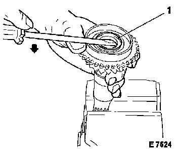
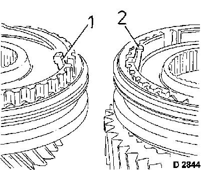
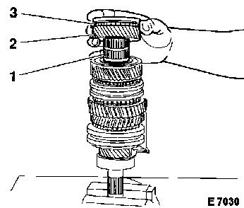
Lever seal ring (1) out of from main drive gear.
Needle roller bearing and, if present, spacer from main drive
gear.
 Inspect
Removed parts for damage and wear.
Caution
If auxiliary shaft gear cluster or the gears are damaged,
replacement of the whole gear cluster is recommended to avoid
running noises.
|
|
 Assemble
|
Before assembling the main shaft, complete synchromesh bodies.
Only one version is described on the following pages since this
operation is the same for all synchromesh bodies. Identification
and special installation position of the respective synchromesh
bodies are indicated in the assembly of the main shaft.
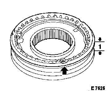
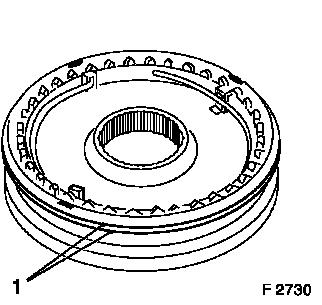
1st/2nd synchromesh body, identification: 1 groove (arrow) on
shift sleeve, overall width (1) is 24.0 mm/0.94 in.
|
|
Caution
|
Do not mix up sliding blocks.
Different sliding blocks are used for the 3rd/4th synchromesh
body and 5th/reverse (1, ball-type version) than for the 1st/2nd
synchromesh body (2, narrow version).
|
|
Caution
|
3rd/4th gear synchromesh body:
Identification: 2 grooves (1) on shift sleeve, small diameter at
inner teeth of synchromesh bodies.
|
|
|
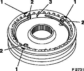
The 4th gear synchroniser spring is interlaced by 10 mm/0.4 in.
(3). Interlacing points away from contact surface. The sliding
blocks (2) are opposite the counterbore (1).
|
|
Caution
|
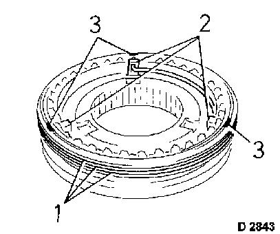
5th/reverse synchromesh body:
Identification: 3 grooves (1) on shift sleeve, the sliding
blocks (2) are opposite the counterbore (3).
|
|
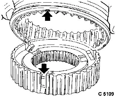
Assemble
|
Synchromesh body
Push shift sleeve onto synchromesh body, insert sliding blocks
in slots in synchromesh body (arrow, bottom).
Caution
Notches on shift sleeve (arrow, top) and raised collar of
synchromesh bodies point in one direction.
|
|
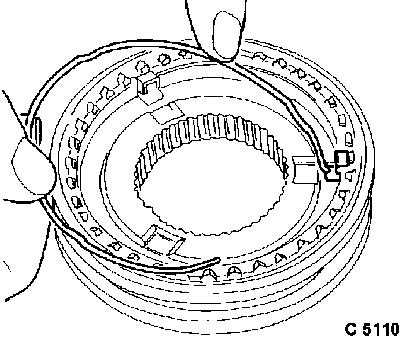
 Install
|
Install synchroniser springs.
Both springs of one synchromesh body are seated in the same
sliding block, but face opposite directions.
Caution
Synchroniser spring of 4th gear is interlaced. Interlacing is 10
mm. The loose end of the spring points away from contact
surface.
|
|
Install
|
Clamp main shaft in vice using soft jaws (output side
upwards).
Needle roller bearing (slotted version), reverse gear and
molybdenum-coated synchroniser ring to main shaft.
|
|
|
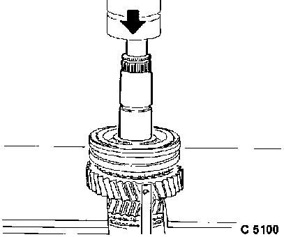
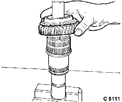
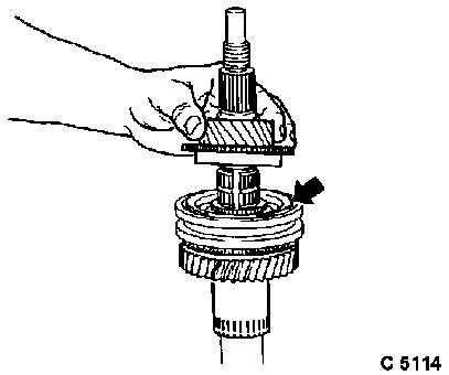
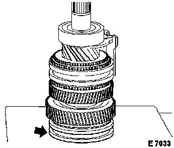
Heat pre-installed synchromesh body reverse gear/5th gear to
approx. 100 °C – use thermocolour pencils or suitable
temperature gauge. Press synchromesh body onto main shaft –
identification grooves point to the previously installed reverse
gear wheel (raised belt of the synchromesh body points upwards).
Only install 5th gear synchroniser ring after pressing on, so that
this is not damaged when pressing the synchromesh body in.
|
|
Caution
|
When pressing into position, ensure that sliding blocks are
inserted into recesses (1) of synchroniser ring. If necessary,
lever up synchroniser rings slightly using screwdriver, so that
they are seated freely on cone of gear (do not jam). If necessary,
align sliding blocks and recesses by turning on the reverse
gear.
|
|
Install
|
Retaining ring for synchromesh body to main shaft, retaining
ring pliers. Ensure it is correctly seated in groove.
|
|
|
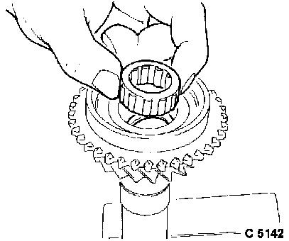
Needle roller bearing for 5th gear to main shaft – spread
slightly and mount over shoulder on main shaft.
|
|
|
5th synchroniser ring (arrow) to main shaft, 5th gear to main
shaft.
|
|
|
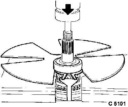
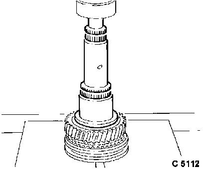
Put on retaining ring (3) for rear main shaft bearing (1),
tension using KM-627-1-A (4) and put on behind 5th gear. Push main
shaft bearing (1) onto main shaft and press main shaft into
bearing.
Caution
When pressing bearing on, ensure that recesses of synchroniser
ring (2) are pressed exactly over sliding blocks of synchromesh
body. If necessary, turn 5th gear.
|
|
Install
|
Clamp main shaft in vice with output side downwards.
Axial needle roller bearing (1) and radial needle roller bearing
(2) to main shaft.
|
|
|
1st gear to main shaft.
|
|
|
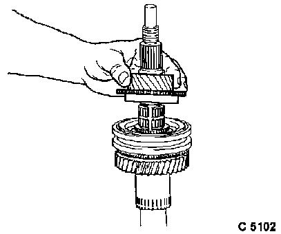
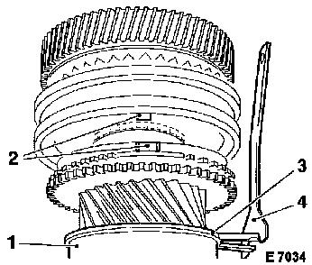
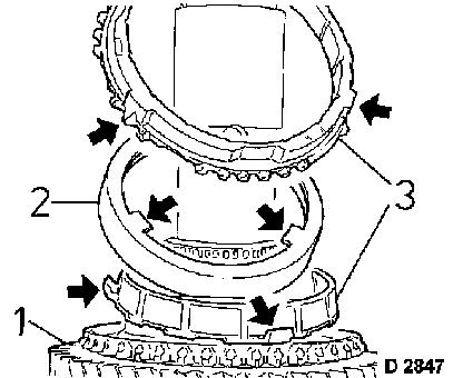
Attach 3 cone synchromesh unit to 1st gear (1).
Align lugs with the appropriate recesses. Note that these are
sometimes on the inside (2) and sometimes on the outside of the
synchroniser rings (3).
|
|
|
Heat pre-installed 1st/2nd synchromesh body to approx. 100
°C/212 °F, use thermocolour pencils or suitable temperature
gauge. Press synchromesh body onto main shaft, identification
groove of shift sleeve (arrow) points to input side of main
shaft.
Caution
The sliding blocks must be seated in respective recesses of
synchroniser ring. If necessary, align by turning 1st gear.
|
|
Install
|
Retaining ring for synchromesh body to main shaft, retaining
ring pliers. Ensure it is correctly seated in groove.
|
|
|
Needle bearing (2), synchromesh body cone (3) and 2nd gear (1)
on main shaft.
See also Illustration D 2847 when completing 1st gear.
|
|
|
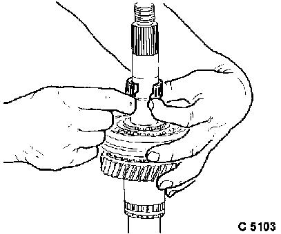
Insert 2 thrust washer halves with lugs into main shaft. Secure
thrust washer halves with retaining ring.
|
|
|
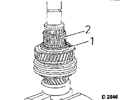
Needle bearing (1), synchroniser ring (3) and 3rd gear (2) on
main shaft.
|
|
|
Heat pre-installed 3rd/4th gear synchromesh body to approx. 100
°C/212 °F – use thermocolour pencils or suitable
temperature gauge. Press synchromesh body onto main shaft –
identification groove (arrow) of shift sleeve points to drive side
of main shaft.
Caution
Press 3rd gear upwards using screwdriver, so that 3rd
synchroniser ring is not jammed during pressing on.
|
|
Install
|
Retaining ring for 3rd gear to main shaft. Install 4th
synchroniser ring only after pressing on.
Grease new needle bearing and if available, place in main drive
gear with spacer washer.
|
|
|
Press seal ring in flush to main drive gear using suitable
sleeve.
Closed side of seal ring faces towards needle roller
bearing.
Assemble transmission, see operation "Transmission, Disassemble
and Assemble".
|
|
|
